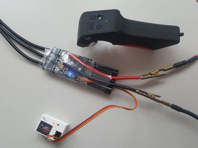
I am testing my parts and I cannot figure out how to connect the remote control properly or set the settings in the bldc tool. As you can see on this picture the remote control is connected (Channel 2) and everything looks good, but when I pull the trigger the motor won’t move. I have the remote from alien. Click on this link to see the description of the remote. In the BLDC tool I set under the category “App Configuration General” PPM and UART ( I tried many of the available settings actually). And under PPM I set “Control Mode” to “Current no reverse with brake” (here I also tried out multiple settings"). Everything else is set to default since the firmware update.
I think the servo signal cable is wrong. It should be where the brown one is
Looking from left on the reciever it should be signal-poitiv and negativ
Looks good. Now switch on the reciever
alright thanks, I will try it out later 
Let me know if it works 
@L3chef Thanks! It does work now! Can you explain what those different modes are? Alle the control modes with “current” work really shity. They only work properly if I move the trigger very slowly at the beginning otherwise the motor just kind of gets “stuck”. The “duty” and “PID” modes work really well, but I could not spot a difference there. Do you know the difference?
Great!  It’s been over a year since I last played with bldc tool, so I’m not the right person answering your qurstion… Maybe @Jinra or someone else could help you with that
Current is the most natural feeling mode (and best in the default BLDC tool IMO). Running it on the bench is different than how it’ll perform when your ide. It applies current to the motor and will spin at full speed once load has been overcome. When testing on the bench, there’s very little load so it spins up to max RPM straightaway. This won’t be the cause when you actually stand on the board.
Duty and PID control control the RPM of the motor directly, but also have the drawback of managing that RPM through the throttle. This means that while accelerating would be okay, letting go of the throttle will cause the board to brake.
Duty cycle controls the % of throttle to voltage in the range of 0-95%. 0% duty cycle = 0 voltage, 95% duty cycle = max voltage.
PID control relies on configuring a target eRPM in which 0% throttle would be 0 erpm and 100% throttle would be the configured target erpm.
What’s the calculation for max erpm?
You can use an esk8 calculator to get your intended max erpm

Thanks
i have no idea how to create a new thread so im responding here and hoping for the best. When i connect my receiver to my vesc it powers on and pairs with the remote control, but my inputs have no control on the motor. I checked the servo cable and its all just as you guys said it should be. Its my first build so it might be something super simple.
You have programmed your vesc I haven’t you? Make sure you’ve thoroughly read up on how to do so.
Also, as a brand new user you cannot start threads yet until you meet certain requirements, I forget what they are. Something about read time and time since registered.
yeah i used the bldc tool to set up the vesc, ill watch some more tutorials on it and report back

