The Torque Boards 6355 motor product page states that the motor wires are:
Blue = A
Black = B
Yellow = C
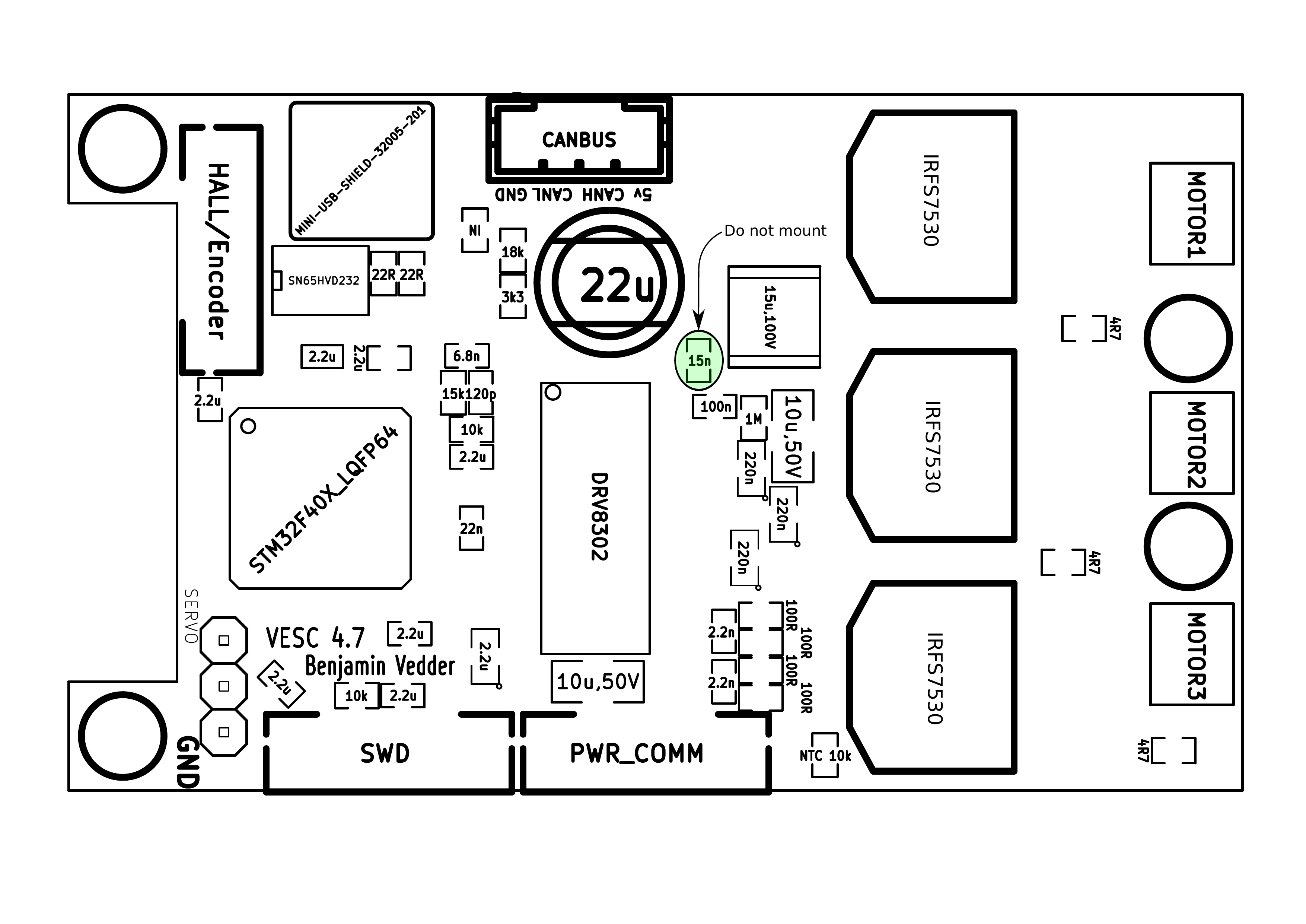
However the VESC does not appear to have any markings as to which wires belong to which phases.
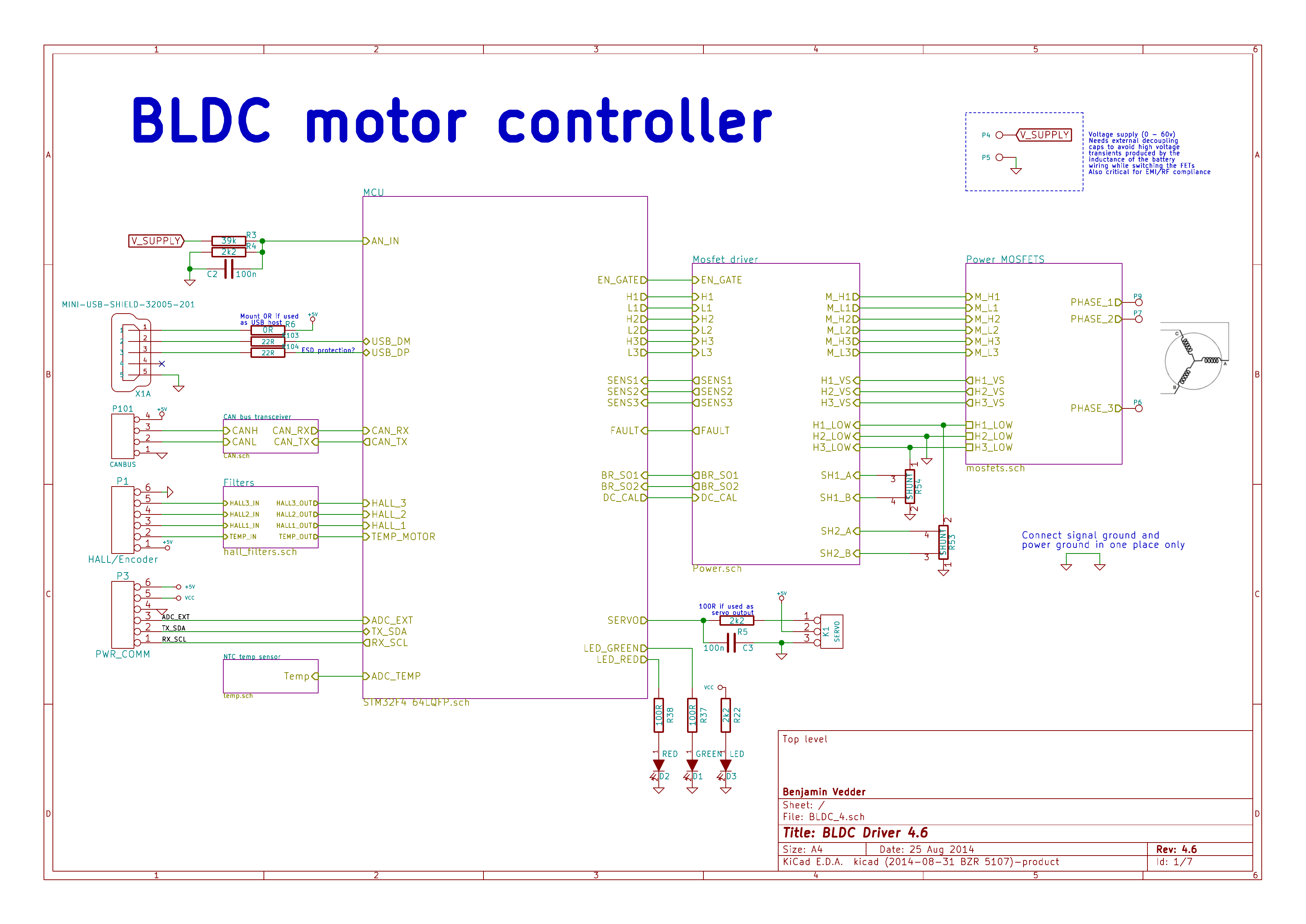
There are pad P6, P7 and P9 on the VESC intended to be connected to the motor.
Does anyone have a similar hardware configuration (VESC 4.12, Torque Boards 6355 motor) running in sensored operation that can shared their wiring (I.E. blue, black, and yellow wires from motor are connected to which wires on 4.12 VESC)?
Hello welcome to the forum, where color truly does not matter, usually. Your going to run motor detection on the vesc tool app, I prefer using a desktop rather than phone or whatever. So hooking up the phase leads doesn’t matter. It will work out.
It’s my understanding that for sensorless operation, the order that the wires / phases are attached does not matter but it does matter for sensored operation when you attach the header carrying hall sensor information from the motor to the VESC (atleast according to the TorqueBoard’s response in Fried 6355 motor? Fried 6S ESC? Help me diagnose please!).
Is the VESC tool (https://vesc-project.com/vesc_tool) able to detect mismatched phase connections? Could I use that to debug my problem?
No need to worry about the phases, you really can’t make a mistake there.
Detection will actually detect where the sensors are at and will turn your motor in a certain direction.
If that motor direction is not right, all you have to do is swap 2 (really any 2) of the phases and it will go the other direction.


