I’m just waiting on my spot welder to arrive to begin work on assembling my first 10s2p battery pack. I’m also starting to order electronics, just ordered a Flipsky dual VESC 6. I decided to rough out a wiring diagram to get an idea of what I need and verify my general idea for being able to upgrade my battery capacity down the road.
Can anyone verify if this will work? I’ve read threads where people mention it is possible to to use one BMS(I ordered a 40A rated one) in charge only with two identical packs. Also I’m unsure about what amperage fuse to run. Using a battery calculator, it says the max motor draw should be ~70A, but it also says that my pack is rated for 40A peak discharge. So I’m assuming to protect the battery that a 40A fuse would be ideal.
fuse the charge port is more important than fusing the load as you VESC will protect from over current. The only use for a fuse on the load side is short circuit so I’d rate it at least 30% over the max battery load think peak burst discharge. 80a 100a 150a are the kind of ratings I’d expect. If your fuse blows you lost your brakes!
why have you got 2 positive and 2 negative coming out of both battery
If it’s charge only BMS then 10AWG is total overkill for a charge current that’s only a few amp.
Mixing old and new cells in parallel is bad you end up with unbalanced cells in you P groups. BMS can only fix the S group imbalance.
Why is the power flowing in and out the volt meter. A volt meter only needs a ground and pos supply no load out
IMO 10s2p is just to small for a Dule drive you be running them cells so hard with huge volt sag.
10s3p is pushing the 18650 but is manageable if you prepared to live with the sag and the fact your running the cells hard and will have reduced life span. 10s4p is we’re things start stabilising.
Charge only BMS so load neg come from the battery as well the BMS only needs - to see the cell for balancing not for discharge protection as this is bypassed.
I’d also remove the xt90 between the BMS and battery if you disconnect them when the balancing cables at connected you fry the BMS
Thanks for the feedback! I think I might just ditch the fuse all together like I see a lot of people do on here.
The two pos/neg connections are just for the diagram’s sake, the leads to the VESC will be in parallel with the battery’s leads.
I had just figured since I’ll have the 10awg, might as well just wire up the whole power side with it. And I’ll be sure to ditch the xt90 in between the BMS and battery.
After your input and running some more numbers on potential range, I think I might just bite the bullet and build a 10s4p from the get go.
I have 3m worth of nickel strip, should I order some more just to be safe?
All depends what nickel strip you have and how you using in on the battery. how many layered you need to carry the current. what you connecting the Parallel groups in series with. I’d recommend looking at flat tined copper braid if you haven’t all ready.
Is there any advantage using that copper braid for the series connections over the nickel? I was planning on running one strip across the cells for the parallel connections, and then running 4 “bridging” strips for each series connection
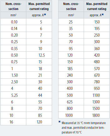
4 layeres of 10mm by 0.15 nickel strip is 4*6=24 amp
10mm by 1mm flat tined copper braid is 6mm2 55-63amps aprox
14mm by 1.5mm flat tined copper braid is 10mm2 75-85amps aprox
Copper has s much higher current carrying capacity.
Copper braid will allow the battery to flex a bit. Nickle strip has no give of the battery flexes it will put strain in the joints.
Think about what current is flowing from what cells and how it’s joined like the pic above.
There is no wright or wrong way of doing it in DIY every thing has its advantages and disadvantages. It’s all a case of using materials, design and construction in a way that minimises the disadvantages. I’m trying to avoid saying doing it XYZ and only suggest things for you to look in to that you might have missed in your research and make your own mined up.
Sorry to bother as I’m not really competent about electric/electronic/wiring but wouldn’t be a good idea to have 2 separate electric circuits to have better redudancy/safety (it’ already the case except between battery and vesc)?
Personally I’d be agains it as it cause more danger than it worth IMO. Think if a lost a power cable and it was floating around you enclosure shorting-things out but the board still works so you keep riding it. I’d prefer it to just stop working and fix it before it dose any more damage.
Then there’s running 2*12 awg wires in parallel to increase the current capacity if 1 had a bad connection most of the current will flow down the remaining good one over heating it and big volt sag but the board would still run so you keep going over heating not only the cable but it transfer the heat in to other components as well.
A real world example smoke alarms have to be dule power supply EG battery and mains powered. Because you don’t know when you have lost one it’s power supply’s it’s law it needs a way of telling you the issue of missing power supply most commonly by a annoying beep untill you resolve the issue.
Some people believe in not having discharge BMS as if it activated it would kill the power potentially saving the board but what happens if your doing 50MPH down a road and some one pulls out in frount of you and you BMS had detected a over current and shut down. No brakes BOOM. On the other side what if your had a charge only BMS When a over cure occurred because you VESC had sorted and it caused a thermal runaway in the battery and the hole board sets on fire. It’s personal opinion to whats most important for you to what way you go.
Advise is some thing to be listens to it’s up to you to decide with parts work best for you and to follow and witch parts to ignore and discard.
I found this build guide video and really like the overall design, especially how flat the pack is and how it is able to flex: https://youtu.be/fEV21DIVQZA
I were to use his design with 10 AWG wire bridging the serial connections would I be safe?

 And to clarify his story about load;
Load positive will come from the battery directly. Load negative from BMS
And to clarify his story about load;
Load positive will come from the battery directly. Load negative from BMS


 Think about what current is flowing from what cells and how it’s joined like the pic above.