Lighting and battery capacity indicator.
I wanted a screen on my board so I could see how match power I have left in my battery’s. so I ordered a special display wat would indicate my battery capacity. This display support up to 48v (10S) and you can set it with a switch between led battery’s, LiPo and lifePo4 battery curves. So this screen is perfect for wat I wanted. It also look pretty good for my taste.

I wanted to mound this display on the front of my board above the trucks. My board is originally a board with trucks what go true the board. But to make a little more clearance I moved the trucks under the board. So now I have a pretty big hole there. I think that this is a perfect place for a battery indicator and a few buttons.

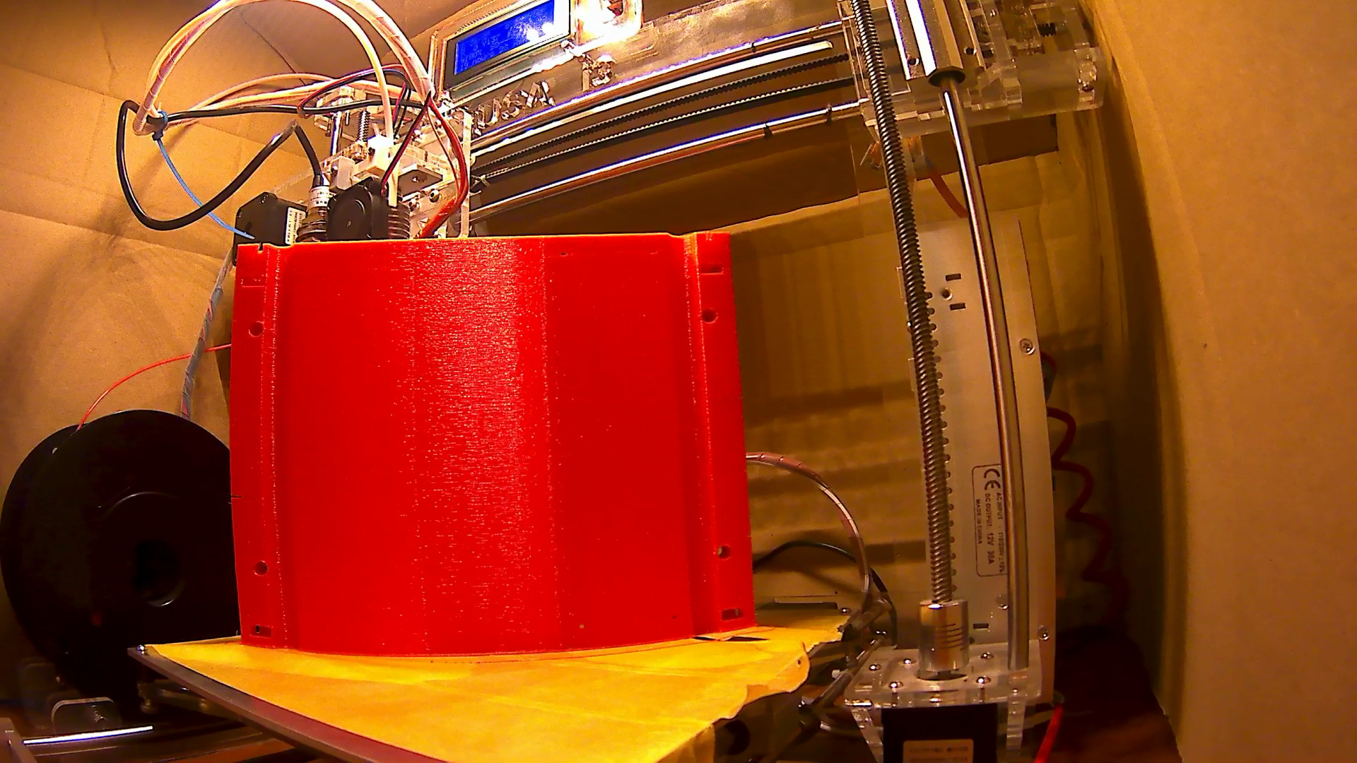
I printed it, sanded it a little bit and then painted the print.

I only have to make a few holes for a screw so the screen stays on its place without the duck-tape…
wiring of the screen is pretty easy. Just 2 thin wires of a UTP cable Is enough to measure the battery’s capacity.
Because you don’t want to hit a hole in the road when you riding with 38KM/h in the dark, and also because it would be assume, I wanted to fit a head and tail light on my board. So I ordered a few super bright white and red led’s.
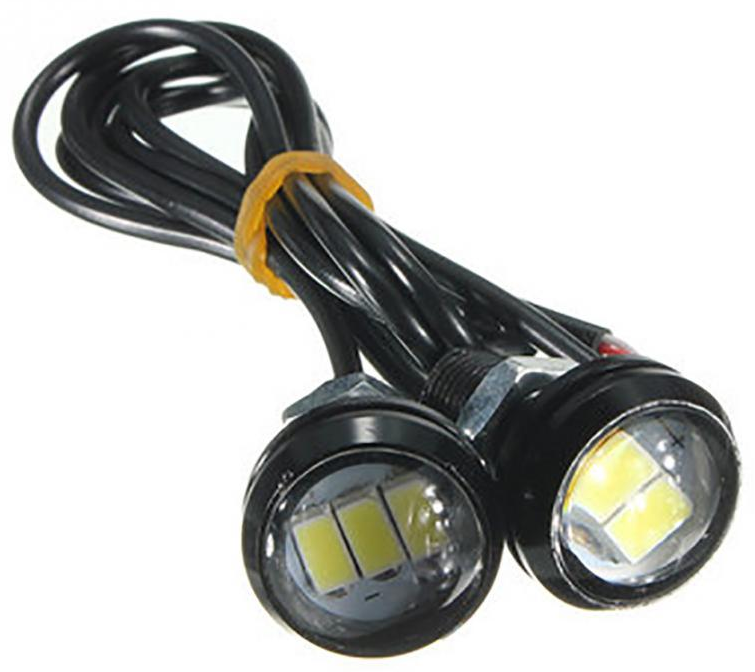
To mount 2 of each led on my board I designed and printed a light holder:

And also painted it black.
I could just simple put the led’s trough the hole and tighten the knot on the body of the led.

Now I needed a way to power the led’s and turn them on and off. The led works on 12v. so I needed a way to step down the 36V that I get out of my battery. So I used a simple stepdown converter and set it on the needed 12volts. I didn’t now if this converter would manages these voltages because it’s actually rated on 36v but we all know that a fully charged lipo is about 42 volts. But is is holding until now so that’s nice.
Like you can see in the image with the battery indicator there is a button next to it. This is a little momentary switch what gifs a signal to a Arduino. This Arduino also gets power of the 12 volt’s of the converter and switch with the help of 2 mosfet’s the front and back lights.

Why did I use a overkill microcontroller ? because I’m planning to add a bit of RGB strips on the underside of my board. That’s why I have a hole for a second button next to the lights on button. Next to that I want to put in a Bluetooth module and connect these with the Arduino. With the help of a little app I can control the RGB and brightness of my front and tail light. And maybe I can even find a way to interface with the Arduino and the VESC. Bud that’s for far far later.
But for now, I think the lighting looks assume.


 !
!
In the dark it look even better… (pictures coming)


 !
!

 !
!


