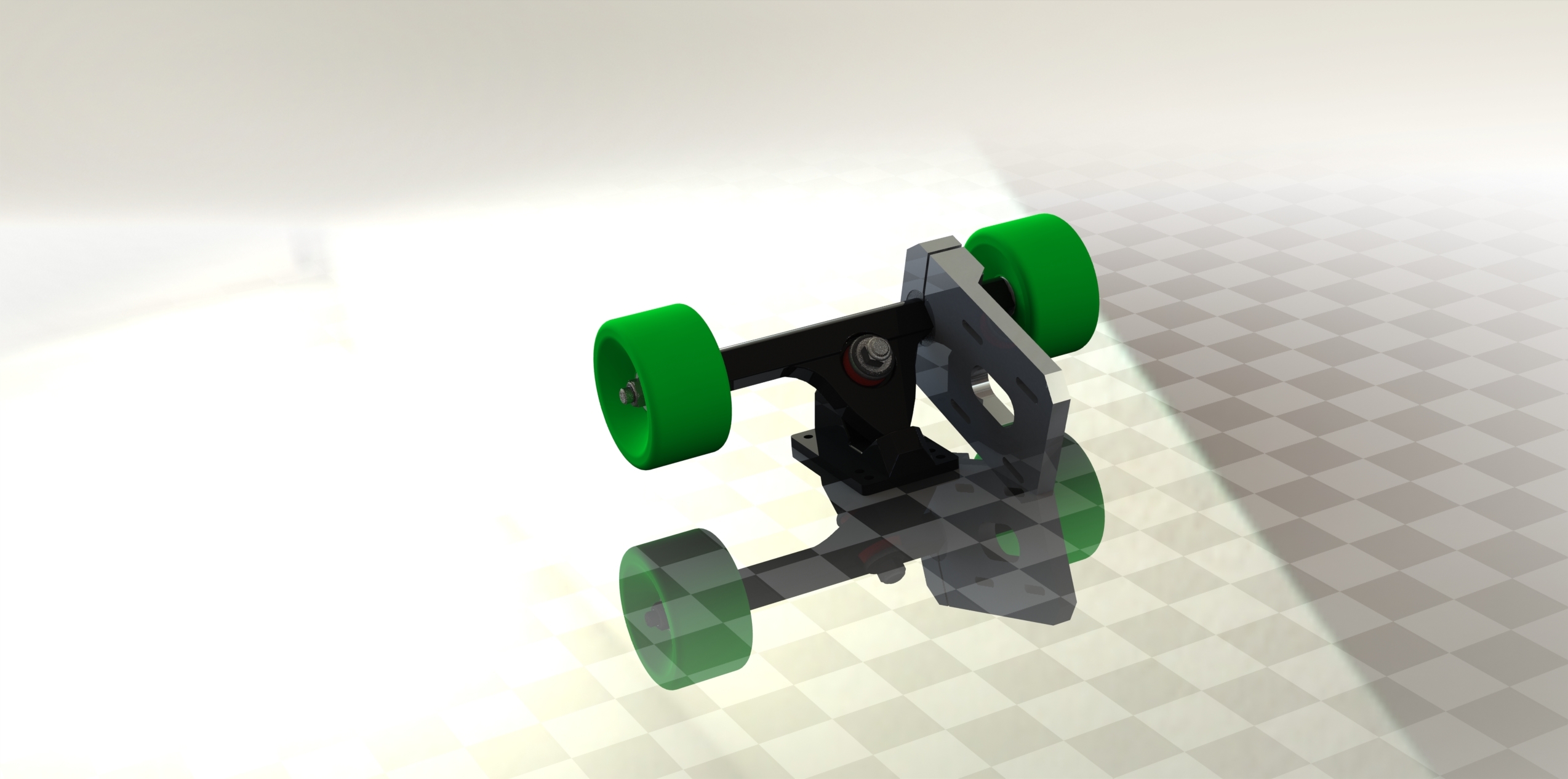
In my continual effort to give back to the community, I am posted my motor mount design files and rendering for you all to make/work on/admire. Once I have received the actual mounts I will post more design files. For now, I am only posting the SolidWorks files, and maybe a couple other formats. Let me know if you want me to post any other file formats. I am hesitant to post formats such as STL since I have not yet received the mount and don’t want someone to make the mount and have it be off by some tolerances. This mount is for Caliber Trucks The motor mount is under the CC-BY-SA license. Link: http://www.thingiverse.com/thing:1729069 Here are some lovely renderings:


2 Likes
Your mount will drag on the ground
5 Likes
It looks that way but the wheels in the renderings are only 65mm I believe, so with 90mm it will be fine.
I just didn’t want to spend the time making the wheels look perfect since they’re not really important to the overall design.
The holes are slotted, so you can just move the motor back to tighten the belt.
1 Like
Have you actually made this? I dont want to be rude but, it is either on backwords in your rendering or it wont work. Your shaft would have to be 75mm long. It has to clear the rest of the mount before you can clear the pulley / belt.
– yeah it’s on backwards, I didn’t even notice that 
As for your question, no I a going to 3d Print it tomorrow and then get it CNC’d later if it works out. I was just so excited I wanted to share 
Haha its fine. Your mount is pretty close to my design
1 Like
Haha, that was yours? I just googled caliber motor mount for inspiration. I can credit you if you’d like.
No, its cool.
Lol. That’s my old adapter design. JK 
Hey @michaeld33, I had a moment to look at your files and you could save some money but not putting this flange around your truck adaptor.
You could get the mount itself waterjet cut no issues but adding this flange is an extra step that will only add costs, under clamping this isnt going anywhere to begin with.
Also, youre right about these not scraping with 90mm wheels, but you do have plenty of “extra” material at the back there that you could go without if you wanted to, also why not counterbore the holes to allow for the head of the bolt or socket head cap screw to sit within the mount itself. One other thing that would save you on fabrication is the chamfer on the thinner to thicker portion. If this is being CNCed not a huge deal probably wont admuch at all if its a 5 axis cnc but if its being done by hand or in a 3 axis CNC thats going to require a change in set up to achieve that angle. Aditional set up time means more costs to you. It looks better with the chamfer though. Here’s your current mount from behind
Here it is if you were to change a few things and remove excess material.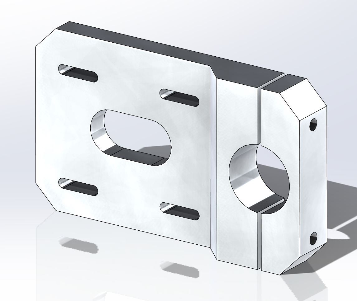
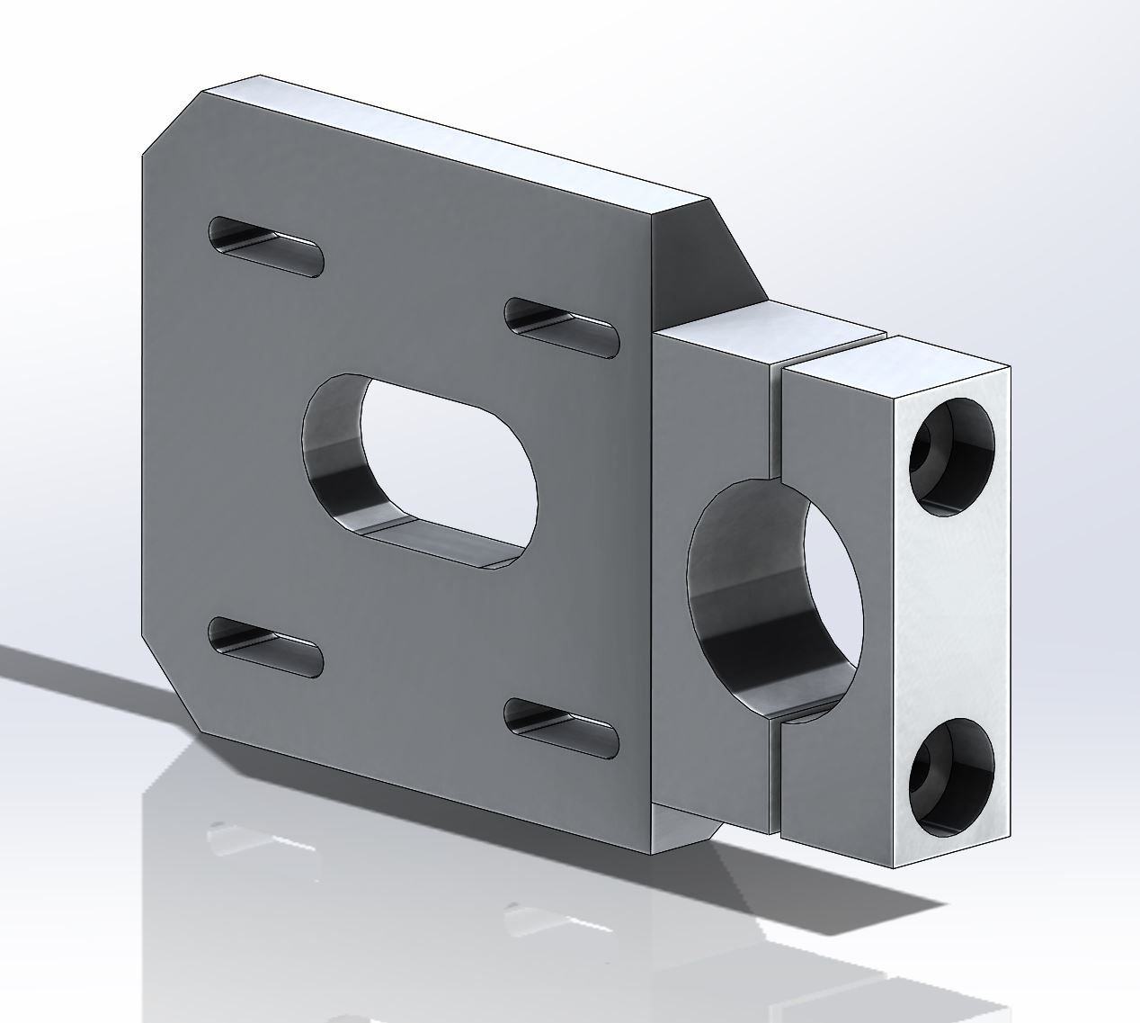
I brought your holes in from 5mm to 10mm and put in a 7mm counterbore for the head of a M6 bolt. onle last thing is 10mm thickness is hella heavy duty. you coule have gotten away with 6-8 and given yourself a little bit of extra shaft for the pulley if youre using a set screw. If you’re using a keyway then it wont matter all that much.
Great contribution to the site though! Once I get my mounts I’ll post them up here as well!
Wow, very nice. Thanks for helping out. I was planning on getting the whole thing CNC’d anyway, so I put the flange on to help prevent the mount from slipping. I put the chamfer because without it the shaft would have to be extra long. This is super useful info! Thanks!
When I refer to the chamfer I refer only the the feature as it does in SolidWorks. You know how you first extruded a large flat plate then the second smaller thicker poration then chamfered the 90 degrees between them? I’m referring to only the last bit. Machining a 90 degree face is easier than 45. Still leave the step. On that note though in your rendering the mount is backwards then. You have the flat face at the back where the motor mounts and the side with the chamfer towards the wheel. You’d have to clear the chamfer because your wheel pulley cannot get any farther than that.
Ahh I see, for the pulley, ok! Thanks. Yeah I realized the rendering is backwards but I didn’t have time to change it at the time.