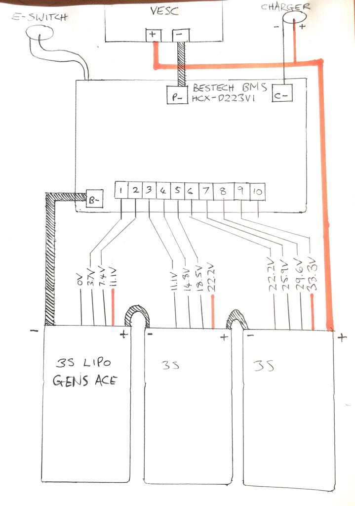
A friend and I connected up a BMS like in the diagram below and things began to smoke after the balance leads were plugged-in.
Where did we go wrong?
A friend and I connected up a BMS like in the diagram below and things began to smoke after the balance leads were plugged-in.
Where did we go wrong?
your diagram looks correct. but there is a fairly good chance that what you did didn’t match your diagram. I reckon you got one of the balance leads out of sequence, and that would have burnt out a row of resistors on the BMS board.
Something about the wiring portion of the balance wires to the BMS seems off.
its the last 3 wires on each pack last wire is red so pack 2 and 3 are wrong dont use wire 1 on any pack im not great on this but thats what i think
I agree with Hornet, while the way you wired the balance leads seems correct, doing it hornets way is just much cleaner as its 3 balance wires per 3s battery which just clicks. The way you wired it in the original can give way to more confusion which is what i think may have happened.
is this a 9s bms or a 10 s bms?
well spoted should be 9s he used a 10s
balance connector usually has (NoOfCells + 1) wires. Assuming this is a 9s BMS that has 10 ports then you have to also wire ground.
EDIT : “Assuming this is a 9s BMS” this assumption was wrong therefore this diagram is wrong. DO NOT USE THIS DIAGRAM.
Im guessing it should be like this:

The port 4 and 7 could be connected with either of the 2 wires i have shown, they should do the same things because they are connected, i have just shown both for clarity.
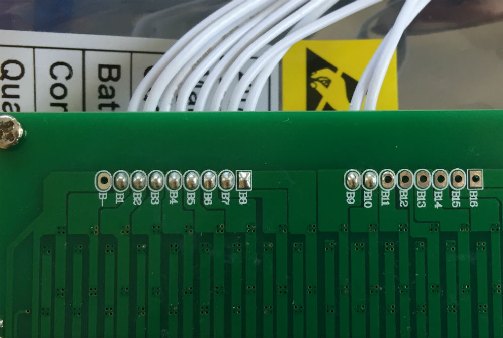
This means in your diagram you have connected 3.7v of cell 1 to ground inside the BMS. If you were lucky you just dumped current through a ground trace and there may be no long term damage. If you left it to long you may have just a burned trace that you could replace, this would be fairly obvious on the PCB. If not there may have been some resistors between between the plug and ground that may have cooked. If this is the case you would see them when you look at the PCB in the BMS.
To confirm that this is what happened i would expect to see the voltage of cell 1 pack 1 slightley lower than the others if you check with a multi meter.
As far as I know all the bestech bms would be 9 wires for 9s 10 wires for 10s
Yea I have no clue about bestech bms’.
I had a look at the product page and they don’t even have any wiring diagrams. Can’t tell if OP bought the wrong board or what, seems weird that a 9s bms would have 10 balance leads. http://bestechpower.com/333v9spcmbmspcbforli-ionli-polymerbatterypack/PCM-D223V1.html
Thanks for all of the replies. Sorry, I forgot to mention the BMS is 10S but we’re only using a 9S pack, hence pin B10 being disconnected.
@ducktaperules, the first pin of the BMS balance connector is marked as B1, so we decided not to connect the balance lead which read 0v to the first pin.
When measuring the individual cell voltages, we kept the black multimeter probe attached to B-, and then measured each cell, making sure the voltage increased by the correct amount (i.e. 3.7v, 7.4v, 11.1v etc). Is this correct?
Ok the pic I put up is right Its wired wrong and you need a 9s bms I’ve wired 10s bestech be for and that’s the way I done it
Yea im fairly certain you cant use a 10s bms for a 9s battery. Dont quote me on that though
You are correct. A Bestech 10s bms will not work with a 9s battery.
Your balance wiring is not correct. You should omit the ground balance wire of each pack and use the 3 positive wires.
thanks for clarifying, i have put a note in my post so that no one uses that diagram
Did u get 2 10s bms