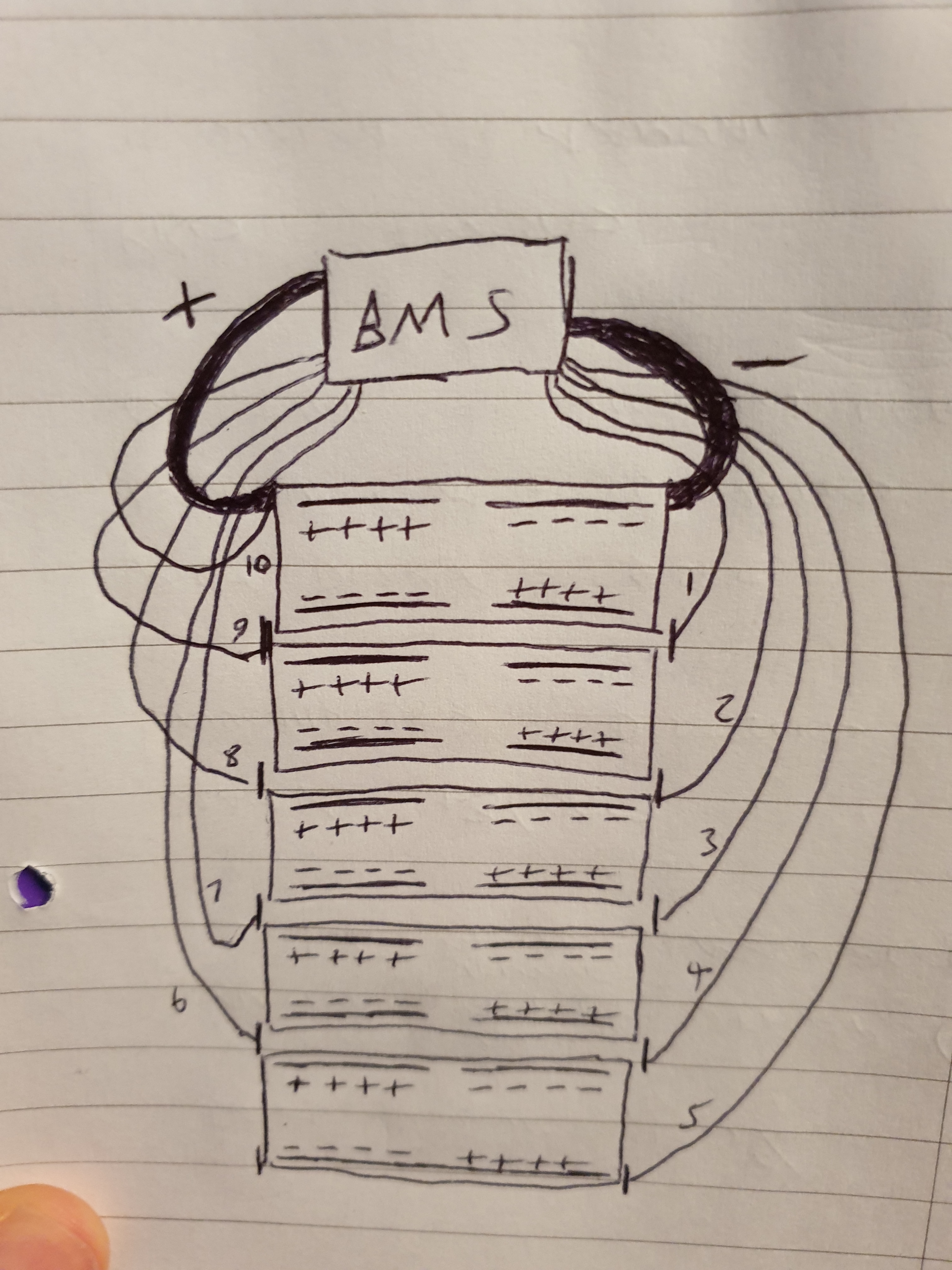
So I’m just trying to plan out the wiring lengths I need, as well as where I’m actually running the wires in my enclosure. I’m pretty sure I have the metal tabs (the solid lines in each NESE) correct, as well as the polarities of the batteries. And it’s hard to see, but if you’re familiar with NESE you’ll notice I have each pack connected by the small bus-bar (the short vertical lines).
However, I’m positive I have the balance wires wrong, cos I only have 10 of them and I know I’m meant to have 11. Not sure where the 11th is meant to go though without it producing a duplicate result… but I’m tired and I may be missing something obvious. (I’m also not sure I have the wires in the right numerical order… the order I used was by following someone elses diagram, but that wasn’t for NESE).
So yeh, please tell me how wrong I am, and set me on the right path 
Hi. Your first balance wire goes to the first negative with the thick wire drawn on your drawing (top left) and thick wire connects to BMS B-
Your 11th balance wire connects to final positive whee you have thick wire drawn but it does not connect to bms, it connects to ESC directly, through a fuse.
From bms P- port it goes to ESC negative and charge negative.
To sum up:
battery positive goes to fuse and then splits to charge port and ESC positive;
battery negative goes to bms B-, then exits at P- and splits to charge port and ESC negative
BMS balance wires goes: B1- to B- of the BMS, B2 - on module 1 and module 2 junction, B3 - on module 2 and module 3 junction … B11 - on module 10 positive
Going from the rest of your reply, I assume you mean to say (top right)? As thats the thick main negative wire.
So it seems I have all my balance wires correct, except that they all need to be moved on +1 because the first one is meant to be connected to the main negative wire (the top right one)?
Also yeh I know the positive power line has to go through my charging port and fuse etc, I was simplifying that part as I hadn’t included the vesc and charger in the diagram. I’ll get to that later, but I think I already have that part worked out 
Thanks for replying!
Yes, top right. My mistake
You need to shift your balance wires by one towards battery -
Thanks, was just checking