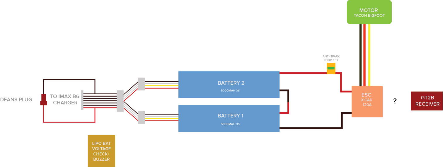
Super noob and I’ve been reading a ton, have ordered everything I need and am ready to start soldering but electricity scares me so I don’t want to hurt myself or ruin any of my components. If someone could let me know if they notice any issues with my diagram then that would be awesome.
Also, a few things I was concerned with when drawing this:
-
with the 2 batteries in series, I’m not sure which battery (1 or 2) goes where on my 3s to 6s adapter
-
I have this lipo low voltage buzzer and I’m honestly not entirely sure where/how to install this. I want this to only be powered on when there is power to the board (using the anti spark loop) but I’m not sure if that’s possible with how I have it set up. I definitely don’t want the buzzer to possibly run my batteries down at night and burn the house down.
-
the gt2b reciever I got - not sure how to plug it into the esc. One, the plug goes in both ways so I’m not sure which way is right and two, there are 4 different spots I can plug it into (ch1, ch2 , bind/ch3, vcc). any idea?
-
currrently Ive watched lots of videos about charging the board through teh balance leads. I don’t have any xt60 connectors- is the deans plugs ok to use for this? also, when charging, does the anti spark need to be plugged in or does it matter? EDIT: I just tried plugging the deans plugs into each other and they seem like a bitch to get plugged in, might opt for the xt60s if they are easier to plug/unplug.
-
Lastly, with the 3s to 6s adapter, I’ve read multiple people say a certain wire isn’t necessary (I believe it’s the middle one, where the black and red meet in the middle). Is this true and whats the reasoning behind it?
-
someone else can chime in who has done this but you might want to consider just getting two cheap chargers and charging the two batteries separately you’ll be able to get it all juiced up pretty quickly with two 5A 80W chargers you could charge at 1C (5A) and have the whole pack charged in less than an hour. Otherwise you’re looking at more expensive chargers and more complications to get the same charge time.
-
The buzzers are typically plugged directly into the balance leads since they aren’t usually in use for discharging (really handy for quadcopters if you don’t have built in low voltage detection on your power board or flight controller). Would need a link to say for sure but if it’s the kind I’m thinking of you basically can just plug the balance lead into the bottom of it.
-
The receiver wire is made in a way that you can’t easily reverse polarity so hard to break it but you can get it wrong. The black wire is ground, the middle wire is 5V and the other wire is the signal line. Usually on the printed circuit board next to the pins you’ll see GND for ground or SIG or signal or something of the sort to tell you which way around it goes usually the ground goes towards the outside of the PCB and the signal is more towards the middle, if you get it wrong no biggie you just get no signal (GND is plugged into signal instead of the signal line, basically since power 5V from the ESC goes through the middle line you can’t accidentally reverse polarity can only reverse the GND and SIG which won’t really hurt anything). Regarding channels it depends on the controller I think Ch1 is usually steering for RC cars and Ch2 is throttle someone with that controller can chime in.
-
XT-60 or better XT-90 are typically easier to work with (60 for 60A 90 for 90A better on the safe side go with the fat plugs).
-
The batteries must be connected to complete the circuit and they are connected in series negative to positive in order to step the voltage up. In doing so the same amperage flows through both batteries so you get no amperage increase nor mAh increase but you get a voltage increase. If you connect them in parallel you get the amperage flow from both batteries separately and their combined mAh capacity but no more voltage.
Better in general to go high voltage low amperage because amperage through a resistor equals power loss as heat. Also power (watts) is a product of amperage and voltage so if you decrease one and increase the other by the same amount you can deliver the same power but have less loss due to resistance.
Thanks for the tips - a couple questions.
I want to have a battery meter (the lipo buzzer alarm if possible) permanently mounted on my enclosure. I don’t want it active when I’m not using the board though. Would the wiring be too difficult/too much work or should I just get a cheapo voltage meter and mount it after my loop switch?
My batteries are going to be connected in series and the charger I got specifically can handle the 6s, just need to figure out the order for the plugs so things don’t get sparkly.
Your diagram is incorrect.
The balance leads are backwards
The balance ground wire should come from battery 1
The outside red balance wire which is cell 6 should come from battery 2
He’s not gonna need two chargers for a 6s system.
There’s no problem charging two 3s batteries in series the way he’s planning.
Eh yeah I figured since the balance leads looked questionable and the lack of electrical experience it might be safer. Also if you get a 50W charger and have 6S can only charge at like 2A or less if you have two of said cheapo charger can kick them both up to charging at a 1C rate… at the higher voltage he’ll hit the W limit of the charger earlier and it will overheat if he tries to charge at 1C. Total valid point though there’s no reason you can’t plug two batteries together to make one bigger battery.
@Namasaki Thanks, so I just need to basically switch the two batteries in the diagram?
Charging slow isn’t a problem for me, I won’t be using this skateboard daily or to commute, pure leisure, and I’d probably rather charge slow in hopes to prolong the life of the batteries.
Cool yeah only issue with charge time in that case is you don’t want to leave the board charged when you aren’t using it so just need to plan in advance to have some time to bring them up to full from a storage charge before you go cruise (and make sure you get your wiring the right way around with the balance leads).
Please fix the diagram and let us have another look at it to sure.
Slow charging is good.
Stopping discharge at 3.6v is good
Stopping discharge at 3.8v is very good
The discharge is the main thing. This is where you can spoil your battery very quickly if you take the voltage too low.
@Namasaki
Here’s an updated diagram of how I’m understanding it.
Thanks for the tips. I plan to discharge to 3.8 to be safe. Is 3.8v ideal for letting the board sit unused? Or should the board be fully charged and sit? These lipos lowkey freak me out.
1 Like
3.8 is actually usually storage voltage I’m pretty sure (maybe +/- a few hundreths a volt, think mine charges them to 3.85) the chargers usually have a storage option where it will bring the cells up or down to that voltage for “safest” storage. I’ve also seen lots of people who have old 18650 cells that have sat on a shelf for a long time pretty charged and barely lost any charge over the course of a year or two but recommendations from RC hobby sites are to put them into storage charge level if you plan to store them for more than a day without use.
Regarding safety for the LiPos the FliteTest YouTube channel has a good video covering how to keep it all relatively pretty safe. Main things are, don’t over charge (not easy to do with a regular charger) don’t over discharge any cell, don’t leave the pack somewhere it could get excessively hot, ideally keep it in an ammo box, or in LiPo safe bags and away from other things that are potential fuel (basically surrounded by metal and/or concrete is best). Sand is the best (home gamer) way to extinguish LiPo fires if/when they occur.
About the voltmeter too personally just got a cheapo one (DROK I think is the company for mine) just make sure it can deal with the charged voltage of your batteries. Have the leads from that tacked onto the ESC on the capacitor board where there were already big solder blobs for the thick wire. So when the ESC has power so does the display.
Yeah that’s better. The easiest way I find to remember which way my balance plugs is that the it should be identical the the way the batteries are connected in series. So if the red wire from battery 1 connects to the negative of battery 2 then the side of the balance blue with the red wire going to te middle should plug into battery 1. And the balance plug with the negative wire going to the middle should plug into battery 2. It’s kinda hard to explain but basically the middle wires on the balance plug should connect the same as the two series wires on the battery
@wafflejock @pat.speed @Namasaki thanks yall, I feel confident enough now to proceed with the assembly/soldering. I’ll let you know if I hurt myself 
Hey thought id add that using a BMS instead of charging it using a LiPo balancer like the iMax B6 is so much easier. I use to have my balance leads just hanging out of my board so I could plug it into my B6 to charge it though the leads would get corroded all the time and it was all around a bitch to do. A BMS is way easier though you have to wire it all up and if you dont have the best skills when it comes to electronics stick with the norm charger. Id also recommend just using a little voltage meter after your XT90 key like THIS one, same thing I use.