This shouldn’t be done right, connecting two vescs in serial?
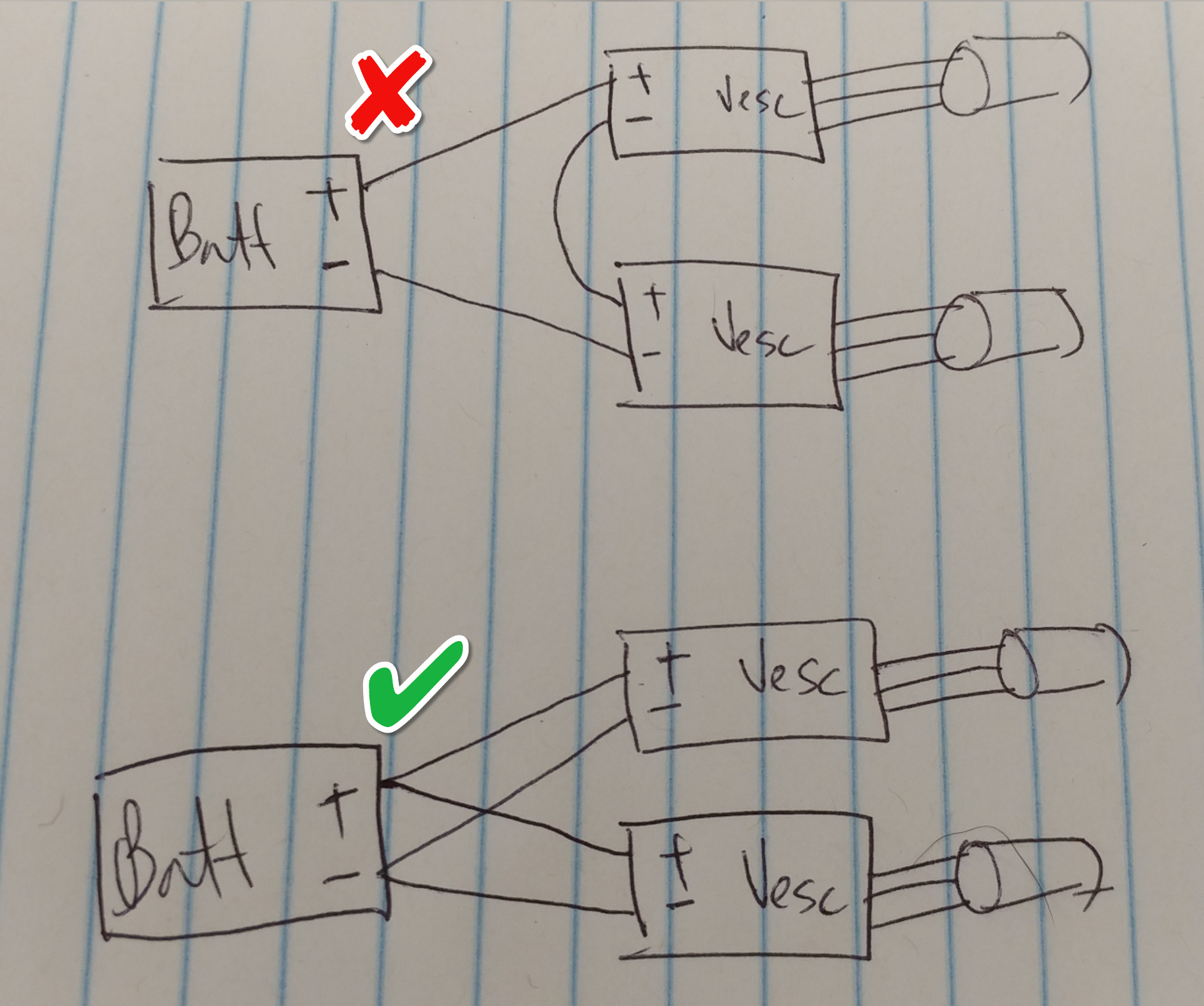
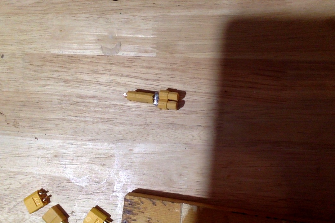
Correct, don’t do that. Use a parallel connector like this one if you don’t want to solder multiple wires together like that

.
Not sure…I have always run them parallel. I’m sure there are lots of trademark reasons not too though!
1 Like
I mean I guess you could if you used double the voltage, but I’m not sure why you’d do that or what benefits or disadvantages there might be.
yea i’m running parallel connectors now, just curious is all.
thanks yalls.
@psychotiller how’s your recovery so far? i know it’s only been a few days.
It sucks…Feels like its only been a few days I guess 
It seems like that wouldn’t work out right… I mean if the VESCs were just resistor loads at a set resistance then it would basically divide the voltage drop across both of them equally assuming they are equal but in the case where the negative from one VESC goes to the positive of another VESC not sure how it would end up equally dividing the voltage unless they were both driving the same power at the same exact time maybe… seems sketchy.
Seems like you could have very low resistance on one part of the VESC in series setup and high resistance on the other and end up with all the Voltage being dropped through the one VESC. I dunno maybe it’s the best thing ever but I’m not going to be the first one to try 

hard pass hahaha
Careful, that kind of thinking can get you in trouble.
1 Like
Happy to see this thread and answers that match what I just did! Instead of connectors I made a splitter wire out of 10awg.
1 Like
Wiring in series will fry the CAN interface on both VESCs. There are probably a few other bad things that can happen but this is what I have seen in the few cases where a customer wired in series instead of parallel.
1 Like
I ususally advocate outside of the box ideas… not this one. don’t do this please.
seems like my kind of recipe for disaster!