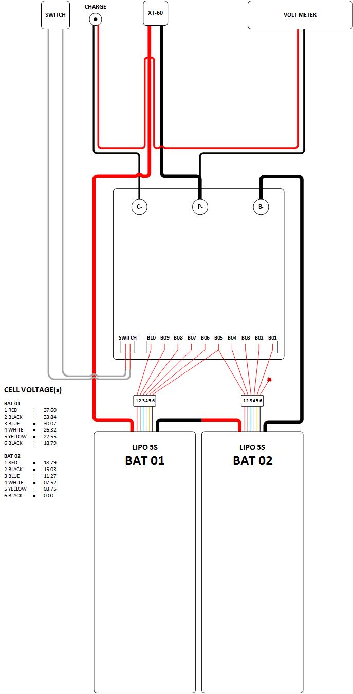
So I’m looking at this BMS on Ebay, looks decent for $22. But I cannot understand this diagram…
Normally the B- port is usually the NEG from the battery pack, the C- port is usually the NEG for the charge port, the P- port is usually the NEG for the LOAD, or VESC’s in this case. If that can be assumed to be true then I assume I would connect as normal and the POS does not connect to the BMS at all, but then it says “the common positive B+”, and It just got confusing as hell. Plus the color codes are non-standard, so I’m not sure if the black or the blue is POS or if any of them are POS!
This looks right to me. The positive (the last wire connected, B10?) Gets used by the BMS for all the positives of the other cells for balancing…
Mine’s the same if I remember correctly.
Although I actually bypassed discharge from the BMS in the end and let the VESC handle discharge limits. Even though my BMS is rated for 80A discharge!
That’s the thing, not sure if am or not. Ill post more when I have the thing assembled and tested. This is a new type of build for me, so I’m trying to take my time.