Heyas. This is my first real post, and first build. As I was looking through the e-skates available on the market, I realised nothing quite fit what I wanted. Unfortunately, nobody had DIY’d what I wanted either, so I had nobody to copy. So after much head-scratching, googling and pestering of the guys on our chat, I came up with this. This build has most of the things I want from an e-skate:
A nice deck in the Bustin Maestro 6. Decks are very personal and I really liked how the Bustin felt beneath my feet. I spent almost 4 hours in the shop standing on every deck I could stand on before I settled on this.
Low to the ground for easy pushing: the drop through mount and the 83mm wheels help with this.
DIY geared drive out of necessity. I didn’t want a rear-mounted belt drive, which would have prevented me from using the kick. I didn’t want hub drives either, they apparently don’t feel so good especially if they’re on a relatively small 83mm diameter wheel. Plus I wanted the wheels to be swappable. Since the drive I wanted didn’t quite exist, I had to put one together. I’m not really a qualified engineer or anything, so this was fairly challenging. More details on the drive in a separate post.
Swappable wheels. Since I was DIY-ing a drive, I wanted the wheels swappable as a feature. These are abec11 compatible.
Acceptable enclosure clearance (about 40mm). Being on a drop through setup, it had to be thin enough to enable me to have enough clearance to clear regular bumps and stuff. I don’t have access to a vacuum forming machine, so it ended up being 3D printed.
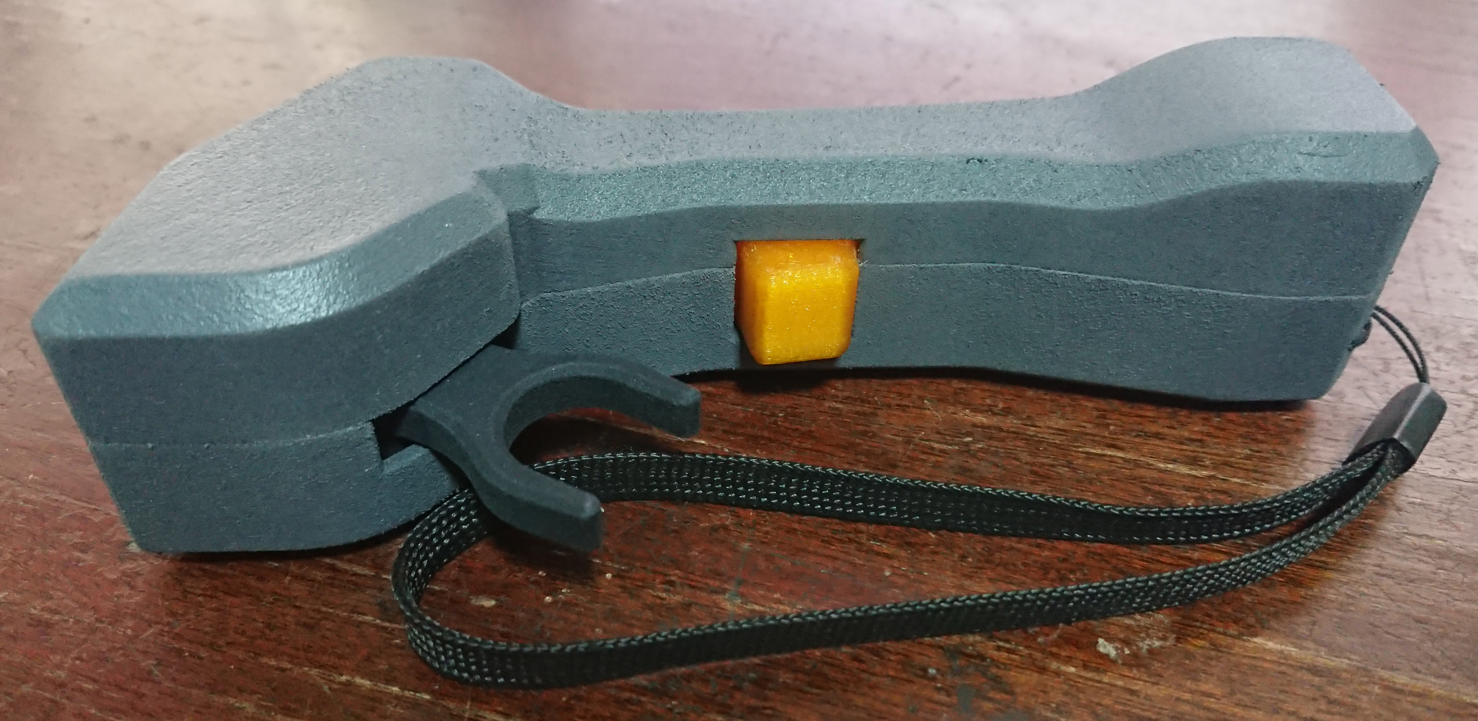
DIY remote with telemetry that is readable from either hand. I really like trigger remotes, they feel much more natural to me and I have better control over my throttle. Also, my brain occasionally does a brain fart when using the regular nub remotes and mixes up forward and backwards. And finally, no trigger remotes felt nice in my hand when I was wearing wrist guards (I always wear wrist guards). Again, since what I wanted didn’t quite exist, I had to make one myself. The remote is heavily based on @ervinelin’s DIY trigger style remote which is in turn based on @solidgeek’s remote, and I owe a lot to lurking on those threads and stackexchange . Again, more on this remote in a separate post below.
Brake lights! I’m DIY-ing my remote and receiver, so why not? WS2812s controlled off the arduino on the receiver, powered by the ESCs.
I started thinking about this build back in March or so, and I only recently completed and maidened her ('tis but a hobby, what can you do). I still don’t know how far she can go on a charge, but she did 11km and the voltage telemetry reads 39.7V, so I think I’m OK for the kind of short fun rides that I intend to use her for. She’s also plenty zippy enough for me, topping out at around 35kph in tests. Pushing is awesome, the gear drives have very little rolling resistance so it’s much less tiring than pushing a belt driven setup. She rides really well, too, but that’s probably just me really loving the deck.
The biggest cons so far are:
She’s not super turny. Avoiding wheelbite even with 83mm wheels on this deck, means the trucks need to be a wee bit firmer than I would like.
She’s not that comfortable at speed. I’m quite happy puttering about at 20kph but if you gun it a bit more the 83mm wheels really remind you that they exist. Good thing I’m happy puttering about at slower speeds.
While the enclosure has decent clearance, the gear drive itself has got just barely enough clearance for smooth asphalt, humps, and small debris (about 15mm). I wasn’t expecting much with 83mm wheels, but I think some of the larger twigs on the ground might literally grind my gears or otherwise do me in.
All the components are crammed inside a tiny space. I am very worried that something will get squished one day and my board will die.
Not waterproof. I’ve conformal coated all of the electronics and done what I can, but looking at other people’s builds it seems that nothing beats a nice continuous enclosure with a nice watertight seal against the deck. I don’t intend to ride in the wet, so this isn’t as bad as it first appears, but it would have been nice to have the peace of mind.
I am currently running her in and monitoring the gear wear. But I think she’s good enough to start a topic about.
Bearing in mind I’m an amateur (hence the name of the board), I hope y’all get something out of it as I slowly fill the topic in.
That is a mighty fine piece of work there! Congratulations. I too have been lurking in the shadows speccing myself the ideal board for me. I am after a pushable board as I (perversely) want to be able to get some exercise and free wheel as much as possible. I’ve not come across the gear drive solution so far, and I was assuming that I would have to use hub motors. Maybe not now?
What I really want is a nice looking board, slim as possible, light and pushable. A cheater I suppose. I guess an Exway that bends. Possible anyone?
Hub motors have their cons, but so does my DIY gear drive. If I was going for a cushier ride and didn’t mind replacing hub motors in their entirety from time to time, I would probably have gone hub motors on a flexier deck like the vanguard. But I don’t like the vanguard feel other than the cushiness, and I didn’t find a hub motor that I liked (except maybe @Hummie’s hubs?).
You could consider the carvon-style motors too. I did but rejected them on the basis that they likely wouldn’t fit on a drop through deck and I didn’t want big wheels.
Bustin has provided their new sportster decks to serve as the basis of the dualomo if you’re interested. But the range doesn’t seem too great… and I still don’t like hub motors.
So here’s the gear drive and how it is supposed to look like on the caliber trucks (just one side for clarity):
This is what is inside:
The drive has a ratio of 2.75:1 (33 teeth to 12 teeth). It has 15mm of clearance from ground to the bottom of the motor mount and drive casing. Wheels can be removed and replaced freely without the use of additional tools other than the standard T-shaped skate tool. The drive itself is covered to minimise dust ingress, but it is not hermetically or near-hermetically sealed.
Problem 1: component selection and fitting. Here’s what I ended up with:
Custom CNC aluminium motor mounts from weerg. At the time, it was the cheapest I could source for 2 pieces that also had multiple threading options. They occasionally give discounts and also may give you one-time discounts for signing up to their mailing list, make sure to explore your options and wait for their mass mailers.
190KV, 4250 can size motors. Unfortunately, I am not sure if I am allowed to share the source for these. You can find motors with these dimensions anywhere but rarely at that KV. While these motors are tiny, I had no choice because of a lack of space, and I figured it would be OK for a dual drive setup that didn’t have to tackle hilly terrain.
6805 size bearings from aliexpress, for the wheel gear. I believe cheaper deals are available and I’m not even sure if these bearings are the best choice for what I’ve used them for.
Custom CNC 2mm carbon fibre plates for discrete gear mesh adjustment (more on this below), from armattanproductions. Upload your dxf and they’ll take care of the rest.
Pinion gear, 12 teeth, mod 1.5, from aliexpress. My order is no longer accessible, but you can look for “1.5M 12T spur gear” and similar options should turn up. Be careful with these aliexpress gears, they’re all over the place. Also, I am told that you can’t have a properly involute mod 1.5 sized gear with only 12 teeth? Something about the maths not working out? But I’m not qualified to assess such things and have just gone with it.
The drive cover and wheel gear (33 teeth) are printed with nylon using the newish HP jet fusion machines. Both were printed from weerg.
The adapter that seats the wheel gear, and the interface between the wheel gear and the abec 11 wheels, are both 3D printed at home using Hobbyking flexible filament. I like the stuff. It prints easily, like PLA, without the need for a heated bed, albeit with some stringing and challenging bridging performance. It also seems to be more tolerant of higher temps than PLA is.
Getting the parts to play nice together was a challenge. If I chose too small a pinion gear, I would not be able to mount the motor close enough to the axle before the motor started rubbing against the truck. Increase the wheel gear to compensate, and there would be insufficient clearance from the ground to the gear. If the motor mount was too thin, I couldn’t get enough material for an M4 screw “clamp” to clamp it on the truck. If the motor mount was too thick, I didn’t have enough space in between them to put the motors themselves side by side. Complicating the motor mount design so that they were mirror images meant that the CNC shop would machine 1 piece each of a left and right mount, rather than 2 pieces of one mount that could be on both left and right sides, which meant expensive CNC costs. Overall, it was a freaking nightmare for a hobbyist with no real qualifications in these matters.
Problem 2: alignment. It’s a gear drive so it kind of needed to be aligned correctly, and the trucks are not precision trucks. In the end, I printed out a jig that took reference from the axle and 4 screw points on the motor mount, and used that to align the motor mount to the axle. Then I printed additional parts to make a “cage”. Once everything was screwed on correctly, the motor mounts would be correctly aligned with the axle. I did have to use some epoxy to get the mount securely on, though .
Problem 3: adjusting the gear mesh. I don’t have the capability to cut extremely precise gears so I had to settle for having an adjustable mesh. I could have cut slots in the motor mount but didn’t trust friction to hold the mesh. In the end the solution I settled on was to cut slots in the motor mount, but have multiple carbon fibre plates with more precisely positioned holes, so that I could discretely adjust the motor mesh but also be assured that the motor wouldn’t shift out of mesh easily.


 . Again, more on this remote in a separate post below.


 .
.

