Hi guys,
This is my first post here. I’ve decided to write it because for the last three months I’ve been spending a lot of time on this forum learning how to build a board that actually works and I feel obligated to share my build with you.
I’m Marcin from Poland, I’m a student of Automatics and Robotics in Krakow. Few moths ago I was looking for something to build during the summer vacations. At the same time I was looking for a solution to avoid public transport and traffic jams in my city. Buying the bicycle was the obvious option but then I remembered my old mountainboard, so here I am.
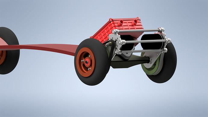
I wanted to create the best mountainboard under $1000, maybe it’s not the most beautiful construction you have seen but the goal has been achieved - board works, it’s fast, powerful and cost under $1000.
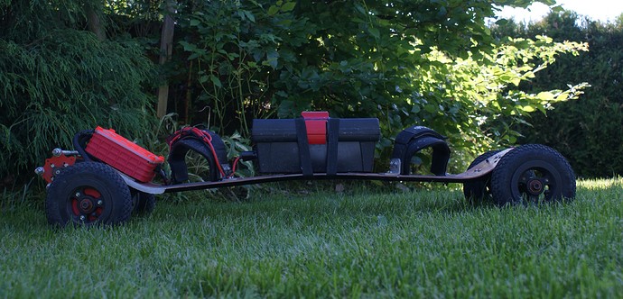
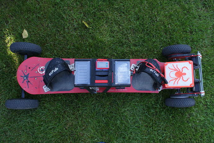
This photo has been taken right after my first few rides, the board works surprisingly well. Yesterday I reached 50km/h (31mph) and drove around for 22km on a single charge (I had to climb several hills).
Full specification of this board:
- Deck - Flexible wooden deck
- Trucks - Spring trucks
- Tires - 200mm (8’’)
- Motors - Flipsky 6374 motors (3500W, 190KV)
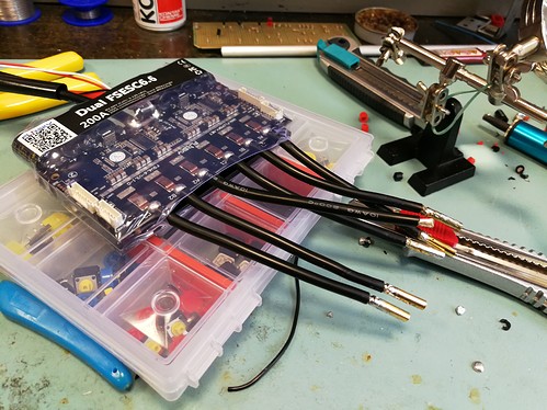
- ESC - Flipsky Dual FSESC 6.6 (100A max continuous current for each motor)
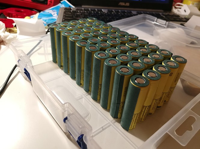
- Battery - DIY 10S5P li-ion battery made from LG HE4 cells (12.5Ah, 36V, 100A max continuous current)
- BMS - for charging only, some cheap bms from aliexpress
- Drive - 1:5 belt drive (15T motor pulley, 75T wheel pulley)
- Remote - Flipsky remote VX1
**I’ll attach a screenshot of a complete excel table with all the components and prices at the end of this post
But let’s start from the beginning:
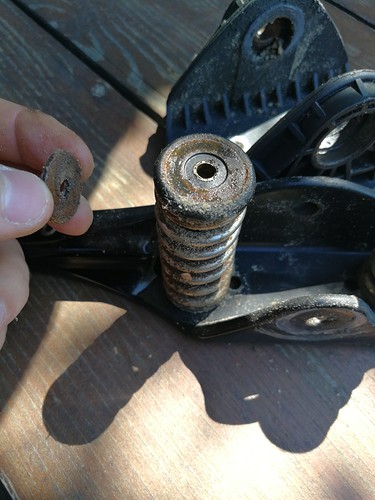
First I had to find this board somewhere in the attic and see if it is still in riding condition, it was used for landkiting, mostly on beaches so salt water and sand left their mark on this board. I needed to completely disassemble trucks and clean every part, buy couple of bearings and change some of the inner tubes. After this little renovation the board looked pretty good.
In the meantime I’ve done a lot of research, I learned most things from this forum and YouTube, especially from those YT channels:
Finally when I knew what I needed I started ordering necessary components and making a CAD model.
Mechanical part:
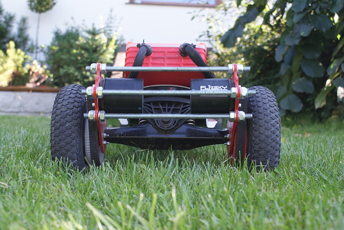
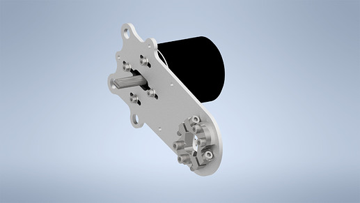
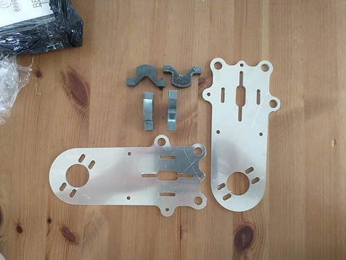
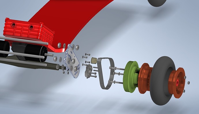
I had to find a way to adapt existing hubs and trucks for the belt drive. I don’t have access to CNC milling machine so I decided to design flat parts that I can make on a CNC laser cutter and assemble them as complete motor mounts (it’s a lot cheaper than ordering a complete 3D part) .
For two small clamps that are made from 10mm steel sheet, I needed to drill the holes (4 holes for each part) for M5 screws. The big part to which the motor is attached was made from 4mm aluminium sheet.
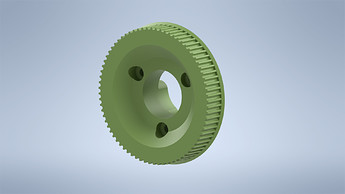
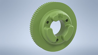
I also designed wheel pulley for HTD belt, 5M, 460mm length, 15mm wide. Pulley slides into the hub and then they are pressed against each other with M5 screws.
In this design I used a parametric model from grabcad.com (link to the model: https://grabcad.com/library/5mm-htd-timing-belt-pulley-parametric-1). It saved me a lot of time so I’m very grateful to the author. Belt fits very well so if anyone is thinking about printing the pulleys for HTD belts I really recommend this design.
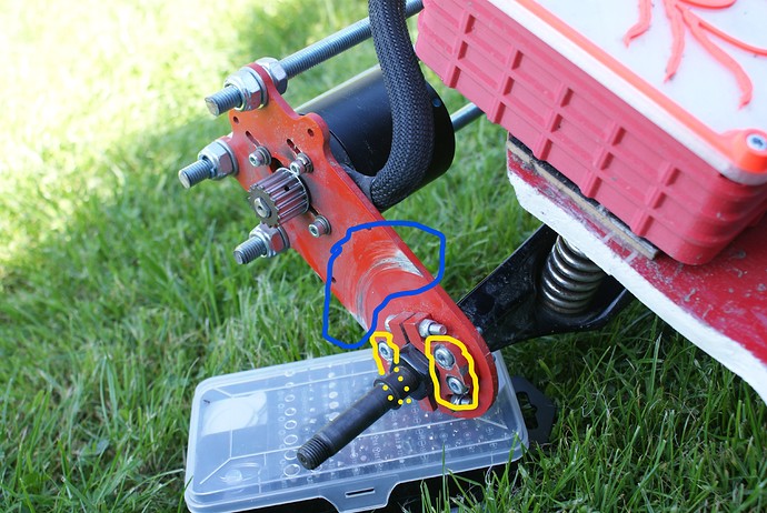
When I mounted everything it turned out that the axes of rotations of the motor and wheel pulleys are absolutely non-parallel. In some cases the belt started to slip off of the pulleys, or the aluminium part of the mount was too close to the wheel pulley and parts began to rub (blue mark).
Fortunately I approached possible problems by aligning the motor mounts so there are three bigger holes in aluminium parts for the M10 threaded rods. By tightening or loosening the nuts on the rods I can adjust the angle of the motor mount slightly and to be honest that feature saved my work. Moreover I had to hide the bolt heads (yellow mark) - they were too close to the pulley as well.
Electronic part:
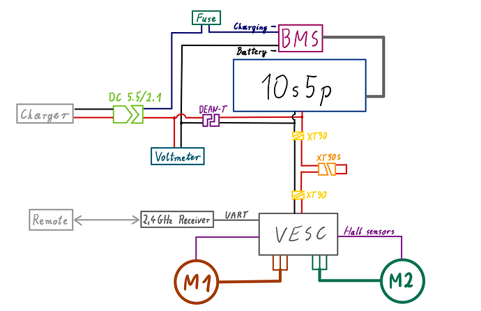
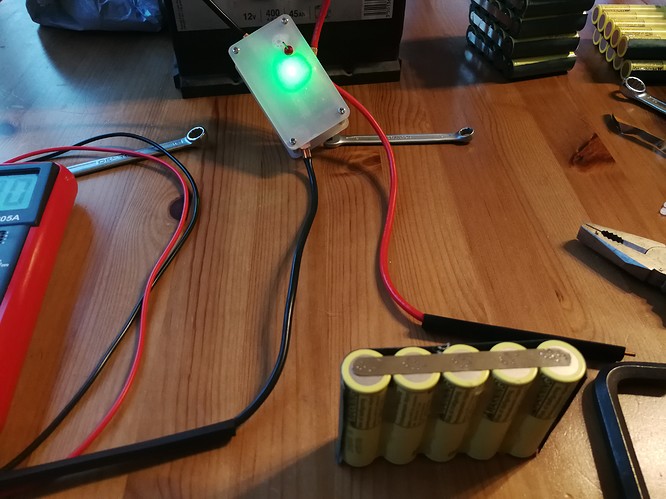
The diagram above should explain how everything is wired. I used 10AWG silicon wires for the Battery <-> VESC connection. The anti spark switch is replaced by the XT90-S connector, which in my opinion it is less likely to break, furthermore it’s cheaper.To make a battery I bought spot welder from aliexpress [DIY Portable 12V Battery Energy Storage Spot Welding Machine PCB Circuit Board Welding Equipment Spot Welding Machine Accessory|Spot Welders| - AliExpress]. After connecting this to the car battery I was able to create the battery pack. Everything worked flawlessly. For the connections I used nickel strips (0.15mm x 8mm), two layers for each connection to prevent overheating. The cells in one series are insulated from the other cells with fish paper, the insulated pads were stuck on every positive terminal of each cell.
Unfortunately I didn’t take many photos while creating the battery, but I did everything in almost the same as shown in this video: [How To Build An Electric Mountain Board - Making The Battery Part 1 - YouTube]
As you can see I also have two extra wires connected to positive and negative sides. They are soldered to the Dean-T connector and used for charging the battery and in the future they will power all of the lights and external electronics.
After the battery was made I just had to solder few connectors and all the parts were ready to be connected.
Cases for Battery and VESC:
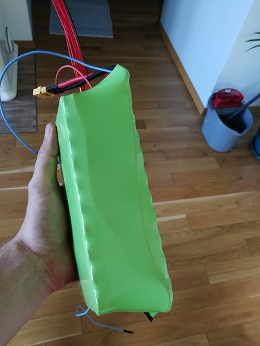
For the battery I used a toolbox from a local shop. The battery fit perfectly in the box, I put some foam to protect cells from impacts and used silicon to seal everything.
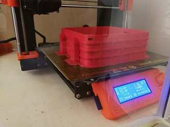
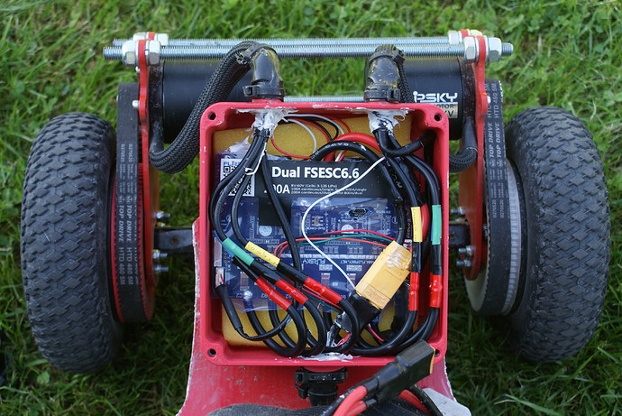
The box for VESC is 3D printed using ASA filament except cover - it’s made from PET-G due to it’s ability to be transparent.
I also put a foam and silicon to VESC box to prevent vibrations and water ingress.
The boxes are attached to the board with hook and loop duty tape, however the battery box was too heavy and loop tended to peel off the board while jumping. Because of that I used some sort of transport lines for holding the box in place and it does the job.
Costs and future plans:
I think that’s all about this build, I had a good time doing this and seeing the results was totally awesome. I do not have any experience with electric skateboards and that board exceeded all of my expectations.
The amount of money I had to spend didn’t exceed $1000 but I already had the deck, trucks and wheels. Also, I need to see how the 3D printed pulleys will perform, it may turn out that I will have to invest in some kind of metal pulleys. On the other hand I did’t use all of the stuff I had bought (ex. 5 pairs of XT90-S connectors) and some of the goods are not single-use (ex. spot welder).
In the table below I presented a complete list of everything I had used in this project with prices. The prices in USD have been converted from PLN (polish zloty) using current USD to PLN rate (3.7886 on 06.09)
Right now I’m working on motor covers to prevent small rocks and mud from getting into the motors. I have plan to install front, rear and bottom lights (ws2812b RGB LED strips). I would like also to mount a screen at the front that would display statistics about the ride (everything will be connected to raspberry pi or Arduino).
Hit me up if you have any questions.
Thanks for reading!

