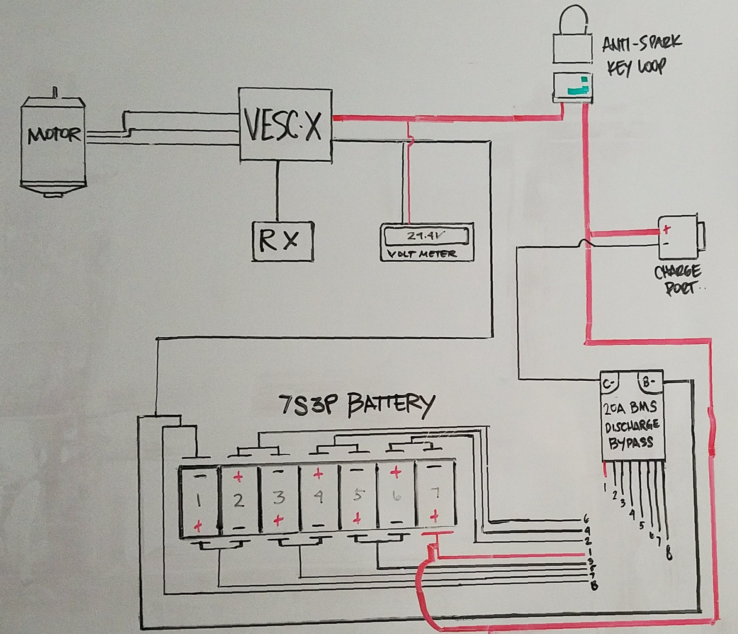
Just wanted to get some Esk8 expert confirmation on the wiring diagram that I mocked up. Based on the many threads I’ve read related to bypassing the BMS for discharge, this is what I have gathered. I will be programming the VESCx to maintain the battery packs amperage draw to prevent the cells from over discharging. The BMS will only be used to balance charge the cells.
No, I don’t think so. Everything except the balance wires is good, except making the lines fatter that need to be 10AWG is helpful, and running a positive to the battery from the charge port and a positive to the battery from vesc/loop key would help to, because one needs to be 10AWG and the other 22AWG. You don’t want 10AWG wire on your charge port.
But the balance wires I don’t think are correct. I don’t know what BMS you are using, but I have a bestech D190 here I am looking at and it’s as follows:
B0 is B-
B1 would be what you have labeled 7
B2 would be what you have labeled 6
B3 would be what you have labeled 5
B4 would be what you have labeled 4
B5 would be what you have labeled 3
B6 would be what you have labeled 2
B7 would be what you have labeled 1, same potential as B+
Electrically it’s the same, but I tend to advise putting the loop key on the negative line because the wiring ls less confusing. Then everything hooks up to battery positive and it’s only the negative side that’s switched. Instead of some switched negatives and some switched positives.
Thanks for the input and suggesting using the appropriate gauge wires. For reference, I have attached the diagram that I received with my BMS. I think I followed it correctly despite I don’t know how to read Chinese.
So then you should have 8 balance wires, where B1 is B- and B8 is B+
Some BMSs omit the first one because they can get the same potential from B- wire but yours appears to have both. So all the wires in the BMS photo would be 22AWG high strand-count silicone-insulated tinned copper wire and the load on the far left would be absent
Good eye @b264
You are correct.
@civic619
The cells are numbered correctly but the balance wires are reversed in this diagram.
You would have cooked your bms if wired that way.