To start off this build, I had to take the Landwheel apart, which was quite easy because I had already done it before to swap out the plastic casing and replace it with an improved one. The ESC and motor wires were pretty easy to get to, so I was able to get the motors disconnected from the metal backplate and ESC case quickly.
This did not amount to much because the battery disassembly and figuring that out was what took the majority of the time. Unfortunately I did not take many pictures during the disassembly of the batteries otherwise I would detail that further. However, I will explain as best as I can in case some other crazy individual chooses to follow the same path. The lid of the case is pretty easy to get off if you know what you’re doing.
Of course for the first one I did not know what I was doing so it was quite challenging. Eventually I found that there were rubber stoppers shoved into the screw holes which I was able to remove one by one by using the tip of a knife and prying sideways. Once I took the outside off, I was greeted by a large plastic sheet.

This is presumably in place to further protect the batteries from punctures and what-not even though the cases are extremely robust. I kept this sheet from each of the three batteries I had just in case I wanted to use it for something else.
Now is where the tricky part arose. I took the plastic sheet off, and below that was obviously the batteries. Much to my dismay, the batteries were built extremely well. The lipo pouches inside were glued with this thick, rubbery, and solid silicon caulk stuff. There was literally no way to possibly rip out the batteries without damaging them. Given that there was a decent amount of room around the outside of the pack, I ended up taking my Dremel with the plastic cutting disc and making very precise cuts around the glued sections so I would be able to remove the batteries. Some of these cuts ended up being very close to the battery so I had to be extremely careful. In addition to the silicon caulk in each of the four corners and along the sides, the battery was also adhesively bonded with some giant piece of double sided tape. It took a little bit of force to remove. I did not really take any pictures while I cut them apart, so the rest will be with the pouches outside of the enclosure.
Here’s a closeup picture that I took of the BMS to see if I could find any information about it online, which I was not able to.

Initially, my goal for these batteries was to assemble them into a new 10s3p pack to see if I could make up for the cutouts that I always got when accelerating with a single battery. After probing around the contacts that the pouches were soldered to, I found the culprit. Two of the packs ended up having a cell in them that was completely dead. Each of these cells was at about 0.3v. I tried to charge them using a lipo charger but they didn’t end up taking any charge.

The third pack actually ended up having three dead cells in it. This was the first pack that I purchased and I think some of that damage may have been from improper use, however, the other two packs were purchased a few months before this project and I made sure to discharge those properly and such.
From this point after I had taken apart all of the packs, I decided to try and test them out with the TB Vescs that I had set aside for this project. I ended up not being able to test the Vescs with them for whatever reason and ended up doing the hub motor setup with my bench power supply.

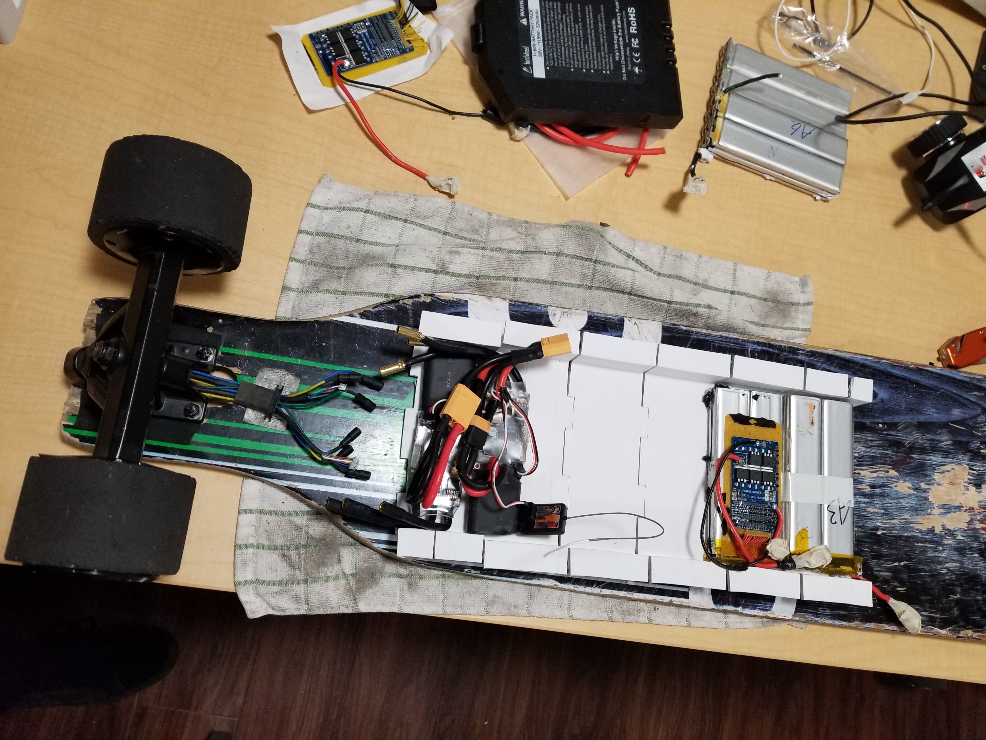
Here’s one of the batteries sitting in part of the enclosure that I was 3D printing for it, along with the vescs and GT2B receiver.
After taking the measurements for the packs and finding the dead cells, I decided the only way I was going to be able to use the packs was to disassemble them to the pouch level. These pouches were all soldered onto a mother circuit board, so it was simply a matter of spending a bunch of time to get them apart.

You can see in this picture that the pouches are a little bit distorted and they have some black stuff on them, that was the adhesive that was used to stick it into the enclosure bottom.


This part was also extremely difficult. Initially, I had no idea how I was going to take the pouches apart because they were all connected to each other with adhesive, and then ALSO soldered to the board. It was almost impossible to get the solder off each of the packs due to the fact that they were glued together and the flat tabs wouldn’t budge. I ended up searching around the internet for solutions to taking the packs apart and it took a while, but I ended up finding someone that used a pretty neat technique. In order to get all of the pouches apart, I wrapped a piece of dental floss around two screwdrivers and was able to slide it between the packs and sLowLY cut away the adhesive between each pouch.
This was an extremely painstaking process and I had to do it 30 times in total in order to separate the 30 cells. It was necessary though in order to get my soldering iron on each of the tabs and then get some leverage on the pack to slide the tabs out of the slots that they were soldered through.
Fast forward quite some time and I have all of the pouches separated and unsoldered. I lined them all up and measured each of their individual voltages to be sure I paired them all in the closest voltage pairs before soldering them in parallel. After measuring all of the batteries I remembered that I had several dead cells, which I had to remove in order to make a functional pack.


I decided that since I was unable to find any 9S BMS’s or 9S chargers that it would be easiest to just go with an 8S3P setup. I wasn’t sure how well the hubs would work with that much of a lower voltage compared to the original 10s, but I figured it would be fine.
The next hardest part came next: soldering the actual pack together. Before actually soldering the pack together, I individually charged each pouch to a matching voltage with it’s other two in the parallel set and placed them together so I wouldn’t forget. In order to actually solder each 1S3P set, I used my vise with a towel in the jaws to hold the battery more or less firmly. The actual soldering for this was pretty tricky, and initially, I thought that I was going to have to use aluminum solder or something special but I realized that the people over at Landwheel had spot-welded nickel tabs onto the aluminum ones that came out of the pouch. I was able to use these nickel tabs to solder to.
On each stacked up parallel set, I was able to solder a piece of 10AWG braided silicon wire. I didn’t have a better option at the time and figured since it would probably have a good amount of current going through it that the thickness would be worth it. I stripped about an inch off of the end of the silicon wire, used my flux pen on it to get a good amount in there, and filled it up with solder in order to make it possible to solder to the tabs.
Follwing preparing the individual wires for each parallel set, I pre-tinned every single tab with solder and flux. The reason for this is because I was still basically soldering straight onto the pouch, and having the amount of heat that it would take to fully heat up the wire and the tab on the pouch would probably destroy it. I set the wire onto the tabs and went at it, making sure to sparingly and quickly use my soldering iron to melt additional solder between each of the three tabs on the positive and negative sides of each parallel pack. Here is the pack after I soldered all of the tabs together. It probably took somewhere around 3 to 4 hours to fully solder everything together due to the sheer amount of work that went into each joint.

After soldering the parallel sets, I fiber taped each of the sets together and then taped the whole pack. After taping it up good, I soldered together the series set with more of the 10AWG wire.

Some of the solder connections look a bit weird but that is just burnt flux; I checked them all to make sure each pack was properly done. The next step was figuring out how I wanted to charge the beast that I had created. I had a bunch of 2S balance connectors sitting around, so I decided to break it into 4 2S3P packs. It took me a while to figure out exactly where to put the connectors so I did my research and it ended up like this:

I used Kapton tape on each of the connections where I attached the balance wires in order to make sure they stayed put. I additionally added fiber tape to reinforce all of the connections in total and provide a way to hold down the positive pack lead.

After this point, I didn’t really take any more pictures because the rest was pretty self-explanatory and uninteresting. I got an anti-spark switch from a deal that Maytech was having with their new rheostatic brake things. Got the anti-spark from @hyperIon1 and it has been working great ever since then. Initially, the brake was supposed to be for this build but they sent the wrong voltage. I finished up printing the rest of the case, connected the anti-spark and battery meter and closed it up. The deck here is beat up to no end and I will probably switch it out eventually.
The board runs great and has way more power than it really deserves to have for an 8S3P build. It managed a top speed of about 22 on the current VESC settings. It hasn’t been defeated by a hill yet either which is quite surprising.
By far the most irritating thing about this board though is its turning. Or lack thereof actually. I don’t really know what to do about it because I can’t mount these wheels and trucks as drop through on this deck due to the shape. The whole board feels very unstable, and even when you turn the trucks it doesn’t turn very well! I don’t know how to fix this really and the only thing I can think of is that the wheels are too big for the width of these trucks. The wheels on it are 92mm. If anyone has actually made it this far, let me know what you think about ways to improve the turning. Do I need a shorter board? Longer board? Wider trucks? I don’t know.
Hopefully, you found this interesting in some way, I kind of just wrote this for the information and for fun.


