GUIDE: How to diagnose a bad series cell in a battery pack

I recently noticed that I have one series cell going bad on my battery pack and just thought to show how this manifests itself, so other people can also test their own packs.

I’m pretty sure the series cell got damaged when I had earlier charged my packs without balancing, so I’m pretty sure it got overcharged at some point and what I’m now seeing is the effect from it. I of course these days charge only with balancing, but due to the damaged cells it takes quite a long time to charge and balance the pack after a run.

So what’s going on with the cells? Well first indicator of something wrong with them is that they are clearly warmer than the other cells in the pack after a run, as is evident from the IR-picture below. This indicates higher internal resistance compared to the rest of the cells, meaning that we are losing more power from the cell as a heat inside it.

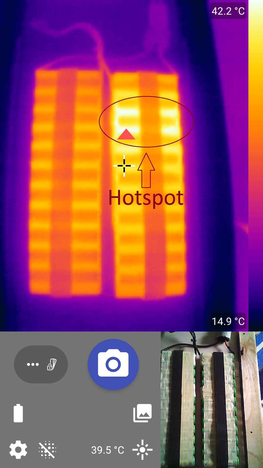
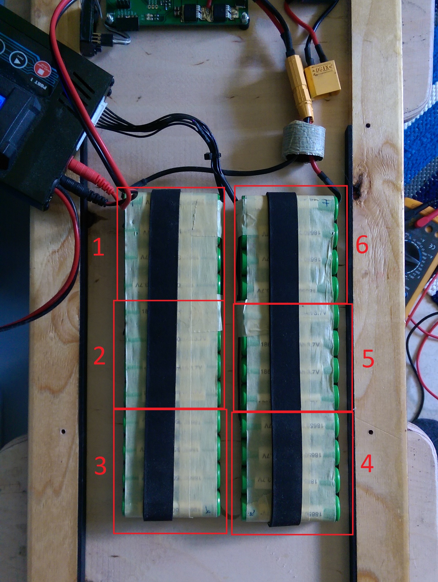
So my series cell 6 is going bad on my 6S4P pack.


Well I don’t have a IR-camera to see if there is a hotspot somewhere on my pack! It’s okay, there is also another quite simple way to see if a series cell is going bad and that is simply by measuring the voltage of each series cell at the end of a run, assuming that you have balanced the pack while charging.

Below are the series cell voltages at the start of the charging. Can you find the difference between them?

Yes, cell 6 is definitely lower than all the others.


Later in the charging cycle the situation actually starts to look normal. But how? Cell 6 was 0.3 V lower than all the other cells and now it’s the same voltage as them? It behaves like it actually has lost capacity and is therefore charging faster compared to the rest of the cells.


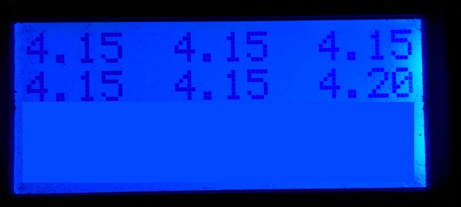
Then the second problem appears at the end of the charging cycle when the balancing starts. Now cell 6 is already at 4.20 V while all the other cells are 4.15 . This is where a lot of time is wasted, because the maximum charging current is only 0.1 Amps, because the charger has to discharge cell 6 at the same rate so it doesn’t get overcharged. So cells 1-5 are going to take a lengthy time to charge up.


So to TLDR, balance charge your pack, measure the voltages after that to make sure that they indeed are what they should be (~4.20 V). Go for a ride and measure the cell voltages again at the end of it. The cell voltages should still be around the same in the whole pack and any large swings could be an indication of a problem.

So the end result is that because of one bad cell in my pack I lose a sizable amount of range. Maximum power delivery is also lowered because the higher internal resistance of the cell causes a larger voltage drop over the cell. This also presents a possible fire hazard with high discharge currents, the cell might possibly degrade faster over time due to the added heat stress and increase the internal resistance even more leading to a vicious cycle.

Conclusion: ALWAYS charge with balancing. Otherwise you might actually be slowly destroying your battery.

6 Likes

Good info, I didn’t know you could thermally detect a cell that was in the early process of dying.

Did you use a dedicated FLIR camera for this (can you give us the model?). I’ve looked at a few of these but they’re always out of the price range for hobby stuff for me, if this is a picture from the phone connected FLIR cameras though it seems pretty good.


Also thanks for the great write up and diagrams good to see what I’ve experienced quantified and graphed :slight_smile:

You are correct about the IR-camera. It is the FLIR ONE, which is the smartphone add-on camera. Paid 200 € (No VAT, because company expenses), but figured that it’s a tool worth that for benchmarking and troubleshooting.

The extra heat is a clear indication that something is clearly wrong with the cell, especially as it’s in a pack made of identical cells. The heat is also a good indicator if you’re stressing you battery pack too much.

It might not reveal the problem thou, if the pack is made from recycled/mis-matched cells. But in this case it’s a good troubleshooting tool.

Well that is a bit harsh no?

As you said in the post you can detect something going wrong with your pack when a series “cell” is at a lower voltage than the rest of the pack. This is exactly the reason why I added balance wires to my pack so that I can check the individual voltages from time to time AND balance charge once in a while. However so far the cells were always perfectly balanced at the end of a ride - and I usually charge without a BMS.

Also we are slowly destroying our batteries just by using them :wink:

What do you use to balance your pack? Is it something that does only balancing or a charger that then balances? In the latter case why not just balance charge every time?

Your heart also has a limited amount of heartbeats before it fails.

1 Like

I have a 10S pack that can be split into two 5S packs. So I can charge it via a 6S RC balance charger if necessary. I don’t for the same reason as everybody: convenience. I don’t want to open the enclosure and unplug everything everytime. Also the 6S charger takes double the time than my 41V PSU as you can only do one at a time.

Interesting theory that the damage could be because of overcharge. I would advise just to build / choose bigger pack so you dont have to reach max voltage to get more capacity every time but I assume not everyone can make that happen…

By the way - what type of cells are you really using? You are getting more than 2.5ah per cell group right?

I charge mine separately but I added extra ports with XT-90 connectors on the side of my enclosure and meant I needed to leave a gap in there so I could reach the balance leads. It’s not terribly inconvenient (don’t have to disassemble anything) but it’s not as convenient as a single connector/plug. Ultimately my charge rate is limited by the wattage of my charger anyhow so that’s sort of moot unless I spend more on a charger or double them up.

That can be done - but my goal was super stealth with a custom CNCed deck. I use a magnetic magsafe port to charge.

Can you link the particular charging port you used? I’m building my own BMS module for my board and I haven’t chosen a charging port yet and I’m keeping my eyes open for possibilities

I am literally using a Magsafe port :smiley:

This was my first self assembled battery pack and it uses LG MJ1s, rated for 3500 mAh, though testing showed more like 3200-3300 mAh (unused cells)

The point of using higher capacity cells is moot at this point anyway, because the cells are internally damaged and unless balanced every time they will continue drift further away from the rest of the cells. I must also admit that this battery hasn’t had an easy life :wink:

Anywhoo, I got that 10S5P pack in the works with Samsung 35Es, which actually tested for their rated capacity, 3450 mAh. I plan to mate that new pack to my BMS module so I’ll have cell level monitoring on discharge and charging + balancing.

yeh, feeling bad for your ‘loss’ here :slight_smile: Too bad the pack went somewhat bad so soon… Do you have an estimate how many kilometers you made with it?

Hm… and it looks like you could go quite a distance then actually with the pack.

On a side note, I have found that this thing looks rather practical:

https://www.banggood.com/ISDT-BC-8S-Battery-Checker-with-Two-85dB-Buzzer-for-LiPo-LiHv-LiFe-LiIon-Batteries-p-1128253.html?rmmds=search

(havent bought it yet, but would be cool to incorporate it)

Maybe, while charging, it could be attached in parallel, to also monitor everything on the display.

Well in a 6S 4P the MJ1 (and 35Es for what its worth) might just not be good enough. These are not recommended to be used at high currents and you have probably used them to their max. That might explain why the cells got bad.

Theoretical power limit for this pack is 22.2 V * 40 A = 888 Watts peak. My ride logs show an average power while cruising at ~260 W, so I perhaps could hit the power peak under acceleration, but these would still be for short times and not continuous pull.

Not going to say that it can’t be that, because I can’t at the moment verify that it is not. The max power pull on the 10S5P though would be 36 V * 50 A = 1800 W. I don’t believe I will be operating anywhere near that. Once I get the BMS module built I can monitor battery current, total pack voltage and individual cell voltages, so I can then diagnose possible problem conditions much more easily.

1 Like

Quick question here before I make the order :slight_smile: I also use no BMS. I trust in the quality cells from nkon.

Yesterday however while I was reading this topic I went to inspect my pack. I have a 10s4p and 9 of the series are within ± 0,02. However I noticed that in one of the series packs there was a single cell out of the 4 which was completely disconnected from the pack. Must have happened yesterday… I abused the board for an hour. :smile:

Can I use a 1s/2s BMS like these: https://www.akkuteile.de/zubehoer/schutzelektronik/ To charge up every series pack one by one ? Would it balance the one single cell in the faulty pack with the other three ?

you can charge one series pack at a time sure. However keep in mind that when you connect the single cell to the remaining 3 and there is a voltage drop between them then they will “autobalance” :wink: by themselves. A parallel pack will end up to have all cells at the same voltage. So it would be better to charge the 3 remaining cells to the same voltage as the single one and then connect them together.

2 Likes

This’ll take quite a while then :confused: I assume its better if I let every series pack charge to the max charging voltage instead of just charging the single series pack to match the others ?

I’m using a charger with a cutoff at 41,4v. Do you think a BMS is necessary ? Couldn’t I just charge the single cell to match the pack and then reassemble the whole pack and let the charger balance it out towards the end of the charge ?