How a BLDC motor works and why a hub motor gets hotter

@devin, our esc are not converters in the true sense (yes, they convert, but… ). Don’t look up converter or step up / down. It’s wrong.

The technique used in bldc controllers is the same as for brushed motors. A commutator is used. In our case an electronic commutator. They create something that looks like AC using pwm. Your pictures above are correct.

And there are no large capacitors to store and forward energy.

Calculation for NO LOAD RPM is the same. Kv * maximum voltage = Kv * battery voltage.

Remember, it’s a theoretical value that cannot be reached by powering the motor off battery and ESC.

I turn my head for two days. Man this thing lit up and I am loving the science.

PB1 hit the nail, KV is KV. A lovely, horribly misunderstood constant.

You can have a similar argument with a Tesla specialist. Their claims used to be that the vehicles were based on variable AC motors which, for the most part, is true. However the hardware resembled BLDC tech on longboards more than you might realize. An active Tesla hacker found that the BLDC drivers only resembled AC signaling but did not product true AC signals as expected from Tesla’s claims. The modulated signals we use for BLDC are neither true AC nor true DC. We may need to find the name or come up with one for the particular sinusoidal effect we generate.

There is a lot of misinformation is this thread. Anybody wanting to learn anything useful should take the information here with a lot of salt :slight_smile:

@VladPomogaev How about correcting it or posting some links please :grinning:

Haha, it will be like the blind following the blind!

@VladPomogaev " There is a lot of misinformation is this thread. Anybody wanting to learn anything useful should take the information here with a lot of salt "

Like everything you read somewhere in an Internet forum.
Would you like to point out which information might be flawed?

Glad if my article made you look into the right direction.

Your mentioning of Tesla also triggered something and I did some searching and found this nice post by a tesla engineer: https://www.tesla.com/de_CH/blog/induction-versus-dc-brushless-motors?redirect=no

In short, tesla uses induction motors which are very similar to our bldc motors. Main difference is that these motors use coils and variable current instead of permanent magnets and control is somewhat different. They are the synchronous motors I mentioned in my original post but driven by converted AC.

BTW tesla uses liquid cooling for their power train and still has to deal with excessive heat. You can’t push a tesla for very long at full power. It backs off in order to protect the electronics and motors.

So indeed the whole Tesla set up looks very similar to what we are using. Gee, we are leading edge!!!

That’s a great article. I remember reading it awhile back.

The reason they use an induction motor is because it’s cheaper to manufacture, just iron and copper basically. Magnets for the same power PMSM motor would be more expensive and the motor would be heavier, but the PMSM has better peak efficiency. Tesla probably put quite a nice amount of RD into developing that liquid cooled induction motor.

Or you guys could just start citing credible sources?

how bout you add some to our knowledge with a credible source? I think wer’re all looking. the quick no citation answer for why a hub motor gets hot is it somehow has to do more work for the same output as a geared system so needs to be bigger. a bigger motor will be more efficient simply until it’s so big the iron losses take over the copper losses. we’re all in copper losses with our small motors.

I saw a video on the production of the Tesla and one thing we dont do that he does and seems really worth it especially with the rough conditions our motors are subject to is pot the windings. I’ve read about potting windings being a boon for dissipating heat but in my experience doing it it was a detriment. I had good fancy resin as well. Wish I knew what he used. Maybe it’s a compromise for the car and ends in more secure windings but a bit hotter and the cooling system can handle it.

potting alone will not help, I think. the heat needs to go somewhere. (in our case) to my understanding not all windings get the same temperature. (hotspots??) correct me if I´m wrong. so potting would distribute the heat better but as its an enclosed system the heat will stay inside the motor. so next step is to get out the heat

1 Like

I would speculate that the reason why hub motor runs hotter, is that it can’t dissipate the heat. So if you’re running the same power to a identical mass and construction materials belt drive motor and hub motor, both should warm up the same rate, but I think because belt drive motors are usually in the airflow all around the can (lots of surface area) it dissipates the heat more efficiently and therefore runs cooler overall. Hub motors have the insulating polyurethane around the can, so it can’t as efficiently cool itself with airflow.

1 Like

I like this discussion a lot but there is a lot of misinformation circling around. I am not an expert on VESC or BLDC motors but in physics and maybe I can clear some of the fundamental misconceptions:

Of course people are right: hub motors are not cooled as efficiently inside the wheel. Even worse: there is rolling friction. Your board doesn’t roll forever because the kinetic energy is lost and heats your bearings, the road and your wheels. So the motor is right where you get most of the friction. But what most people completely mix up in this thread is the following

What actually heats the motor the motor in the first place?

Short answer: Losses! Not the Current, not the total Power.

The Power dissipating into heat is NOT the total power. Let’s consider a simple scenario for now: we accelerate, no rolling friction or air friction. Energy E is conserved, so E (P is the change of E over time), is split up into two main channels: kinetic energy K, and the loss L: E = K + L All the energy that actually contributes to accelerating you does NOT produce heat at this point. It will eventually since you don’t roll forever. But for now it does not. Only L. The efficiency is the portion of E that you can get into K instead of L. This is where @HTownBomber is wrong: a motor is not simply a resistor. The power consumed by the motor is P = U*I but that it not the power that dissipates into heat like in a resistor.

The statement that only P matters, not how you distribute your numbers in U and I, is wrong because the efficiency changes!

One part is electrical loss simply trough the electronics resistance R. The loss due to R is NOT the product of the total battery Voltage Ub, since only a portion of Ub drops over R: Ur. Only the rest of the power is USED by the motor. But the total battery current I passes through R: P = Ur * I = R * I²; This is the reason why we use high voltage transmission lines. You cannot avoid resistance altogether. So keep the voltage high and you increase the portion of Power that you can USE. But, as @Hummie pointed out, this does not apply to the motor windings: lowering KV reduces I but increases the resistance and the copper losses are the same. It does however apply to the rest of the electrical components and especially the ESC is more efficient at high voltage.

Apart from the electrical loss there are the typical BLDC motor characteristics. As I said: I am not an expert for BLDC motors but there are some rules of thumb that you can easily apply. The properties of a typical BLDC motor should look somewhat like this:

http://www.mellorelectrics.co.uk/BLDC-performance-graph.jpg

http://www.mellorelectrics.co.uk/BLDC-MOTOR-EN.html

N: RPM EFF: efficiency P: power I: current

This an idealized graph for ONE specific motor, and this is imporant: for one KV value (RPM/Voltage). One important fact that people should pay more attention to is that the maximum power is not where you find the maximum efficency!

To increase efficiency you should run your motor at a high RPM and low torque. This is why you should use a small motor pulley and a large wheel pulley in a timing belt setup. This can bring you to the left side of the graph, where the efficiency is high.

Also you can lower KV, which should more or less scale the x- and the y-axis. It will give you higher torque at lower current. Therefore you can keep the torque load further from the maximum that the motor can do. Reduce the speed, increase the maximum torque, then you can shift the maximum efficiency to lower RPM.

To estimate what “high RPM” means we can calculate some numbers: The largest gear reduction that you can usually get is around 12:36 . Let’s assume we want a maximum speed of 35 km/h (21.7 mph). At 83 mm wheels this means the motor will run at ~6630 RPM. The KV that you need for this at 12s is ~150 RPM/V (!!!). This way you can run your motor close to the maximum efficiency.

What makes hub motors become so hot? The lowest KV of a hub motor that I have seen so far is around 75 RPM/V, which leads us to a theoretical top speed of 52.7 km/h (32.8 mph)! So why do you not reach it? If you can’t get close to this RPM it means that your load is too high! You run at a regime at too high torque load, too high power (center of the graph), and low efficiency. Your motor will get hot because it wastes a too much of the precious power from your battery pack!

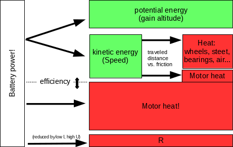
As you accelerate you climb up the blue curve (RPM) and the efficiency climbs up with it. Your motor has a comfort zone. But you can only get there if you don’t use all the torque, that it can offer. Here is a cheesy flowchart to illustrate my point graphically:

9 Likes

I like the graph you posted, helpful in understanding the characteristics of brushless motors, and the disadvantage hub motors have not being able to change the gear ratio. Makes sense to me, can’t just make a bigger hub motor, because the wheel circumference also increases.

@Mathias very good post thanks!

As mentioned above I’m working on part 2 of my article that is going to cover the stuff you mentioned, so thanks for contributing.

I’m also doing a chart that calculates some data based in input. Thinking about it I could use this sheet in order to plot a graph for various motors and extend it and include SPEED. This would then be the theoretical graph that we would have to verify.

BTW:while the graph in your post is absolutely correct, it is somewhat difficult to read and interpret! e.g. the unskilled eye could think that amps is the highest at high RPM while the contrary is true!

http://members.toast.net/joerger/pic2/motorcurve.gif

Would this be easier to interpret?

Yes, didn’t actually make it. The link is posted below the graph. I would also prefer @SimosMCmuffin 's post. It is less confusing. I was already thinking about making calculations like this on my own, or rather a simulation with proper parameters for an e-skateboard. Unfortunately I’m super busy writing a thesis at the moment. I shouldn’t actually be on this board right now… It’s just that e-skateboards seem 100 times more interesting at the moment:

that’s the universally agreed graph :slight_smile:

Not sure how many people really know what it means though, hahaha …

will try to draw the curves for specific boards or setups and showing speed in km/h as horizontal (x axis), then every eSkater can check at which exact point in power he is. This needs some assumptions of course.

Thanks guys for your constructive input!

@mathias, fully with you. At day time I should do some work, in the evenings I rather go for a ride on my eSk8 board than this discussion board and then there is family … :slight_smile: