
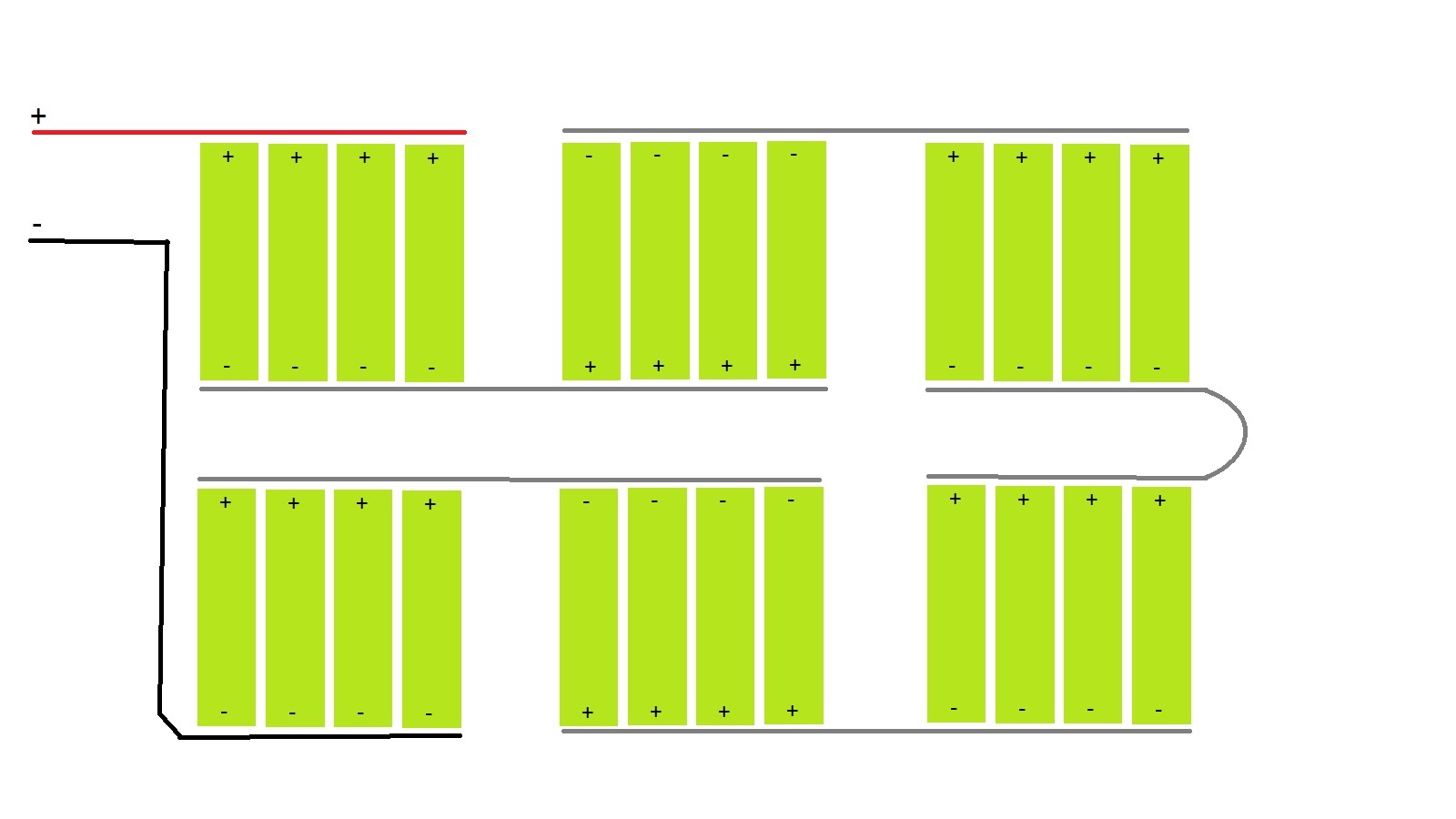
Let’s start with the first pic in top left corner. If this group of 12 cells are part of a 10s4p pack pulling 50amps, the connection between the fourth cell on the bottom and the third cell will have a total of 1.25 amps, the connection between the second cell and third will have 2.5, third and fourth cells will have 3.75 passing. So we have …about 1/40 the current passing through a parallel connector. @Ackmaniac @PXSS this is a common arrangement for a pack and even if we were to use another example from the four I posted the currents will be very similar. What u think?
6 Likes
Each series pack has to provide the total current. The voltage gets added but not the current. So in the first picture the first 4 cells on the left have to produce 40A. The next pack also 40 amps and so on. Only the voltage gets multiplied from which each additional series connection.
Now I understand where your misunderstanding is coming from.
4 Likes
Sorry yes ur right and forgot about that and will be 12.5 amps at the bottom, 25 next, then 37.5 amps would be flowing on that top left pic through the parallel connections. the other examples of batteries above have more series connectors attached to the parallel connections and there will be no more than 25 flowing at most in the parallel connections
I’m having a date with my gf. I will respond to this tonight at some point
This is a great place to start getting some clarification on this topic 
4 Likes
@Hummie You don’t seem to understand how parallel and series connections work. I recommend you do some reading on parallel and series circuits.
The top left circuit is representative to some extent for electronic skateboard batteries. Most people make the parallel packs and then connect the end cell in series to the next group of parallel cells, just like in the top left drawing.
I still don’t get where you’re getting your numbers from, it doesn’t make much sense. Specially since you’re not including equations.
Here is the equation you should be using, which I also wrote in the previous thread. (N-1)/N * I = Max Strip Current N = number of cells in parallel I = total current
That will calculate the current flowing between the first and second cell in “parallel”. The reason there is current flowing is because you need current to flow into cells 2, 3 and 4. It doesn’t just appear there.
Think about it this way, you have four pumps of water (batteries) running in parallel, they need to output 40 cubic feet per meter (Amps) of water(electricity) together. So each pump needs to provide 10cfm. You have a hose that can carry said volume to pump one but then you connect pump 1 to pump 2 with a dinky hose that can only carry 5cfm, then you connect another dinky hose from pump 2 to pump 3, and a third dinky hose from pump 3 to pump 4. Pump 4, although it can output 10cfm, is restricted by the dinky hose you attached to it. Pump 3 can also output 10cfm but now pumps 3 and 4 have to share a hose to pump 2 and then pumps 2, 3 and 4 have to share a dinky hose that can only handle 5cfm and try and put 30cfm through it. The result? The hose stretches and stresses and puts an extra strain in the pumps. It works but eventually you’re going to overstrain the pumps and they will burn out.
Now, same thing with batteries. You can use dinky nickel strips to connect them but you’re going to generate heat and have unnecessary voltage sag which will cause your pack to fail sooner than later.
Ever seen 500 9volt batteries connected? On youtube and a guy turned a very large heavy metal wheel called Big Bethel,. . 9’vs in series
Series Doubles Voltage
Parallel - ah

How about taking spare 36’s and doubling down, if not triple to over 100v. Power a 150# board. Im kinda scared.
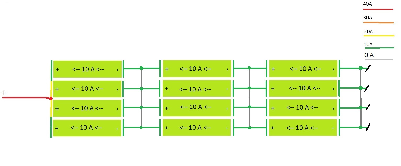
I’m going to add my thoughts on this as well and I’m going to use my own self assembled 6S4P battery pack pictured below, to illustrate.

Here’s an illustration of the battery (without balance leads):
Now, let’s say we had a nice 40 Amps of current so we get an even 10 Amps flowing through each parallel cell. Now the next picture has the wires/strips color coded so they show the current/heat/voltage sag in each segment of them.

As can be seen the heat losses are better distributed across the parallel cell pack. I’ll admit though that having one side heated by the resistive losses in the strip and the other side being cooler is still not ideal, but compared to the hummie’s example where:

Now the most top cell is next to the hottest segments of the wire/strip and will heat up the most and will degrade the fastest of the parallel cells
EDIT: Added internal current flow indication to the cells.
10 Likes
Thanks for the awesome diagram. That’s what I’ve been trying to explain since yesterday.
@SimosMCmuffin Could you please also make a drawing of my battery pack design. Would be great to visualize the advantages.
Edit: for @SimosMCmuffin Here in this post you find the pictures. Be aware that they will have parallel connections as well later on.
Yes, it’s a good setup as you actually have as many parallel wires as you have parallel cells, so you have minimal losses. And ideally you’ll have 0 Amps flowing between the parallel cell connections.
PS. I didn’t know how you were going to terminate the negative and positive ends so I went with my example, but you can tell me if you plan to do it another way, so I can update the illustration.
EDIT: Battery pack termination updated.
1 Like
I wouldn’t say 0A on the parallel connections but close enough to it as long as your cells are balanced when you place them in the holders
Connect all 4 to one wire in the middle. So between cell 1 and 2 there is 10 Amps and from 2 to the main wire it is 20 A. Main wire to 3 is 20A and 3 to 4 10A.
Better hope they are pretty balanced before putting them in, or you’ll have some power balancing happening otherwise ![]()
1 Like
Lol yup. That’s how you make wires disappear
I would rather lean on the: “That’s how you vaporize Li-Ion cells internally” side of things. Wires should be able to handle the currents without escaping into the atmosphere, especially as you’re plugging the cells one by one into the holders.
I evaporated a holder in an experiment. The battery survived just fine. It had some health deterioration but if I remember correctly it was the equivalent of losses through 5 cycles
Did not assume the use of a holder. Did the holder have the spiral springy clip at the other end? That’s what I would suspect to vanish in that case.
The one posted on Ackmaniac’s build. I’ve also evaporated Nickel tabs at around 18A although the spot welding job was sketch
great pics Simon And you’ve pulled out the “practically” zero current through the parallel connectors example I’ve been unable to come up with. appreciate the help and the cool attitude. if there’s confusion about the numbers I posted for the current going through the strip, my first post was an electronics faux pas as I forgot only the voltages add here, but get to my second post and the numbers are spot on using a 50 amp draw as apposed to the 40 Simon is assuming.
what are the risks to the cells in one of the poorly designed packs above? Solely heat in some unlucky cells due to solely their connection having more heat?