Hey there, i am not experienced with creating a pcb but some of the community are.
Could someone modify the current Vedder Switch 1.4 that we will be able to attach a LED direct to the PCB like the torqueboards switch?
Hey there, i am not experienced with creating a pcb but some of the community are.
Could someone modify the current Vedder Switch 1.4 that we will be able to attach a LED direct to the PCB like the torqueboards switch?
Led or led switch?
LED switch 
diy-electric-skateboard-kits-parts/electric-skateboard-on-off-power-switch/
Can’t we already use a led switch the current version of Vedder antispark pcb? I am using a similar led switch as torqueboard with my vedder antispark board.
Yeah I think you can
we need a wiring diagram and a what kind of switch you use if its possible.
@chaka might be able to tell you. I reckon the middle is for the led and the two outer pads are for the switch
Not really. The problem is that the LED wont shine bright enough if you only attach it to the current circuit Design…
I use an led switch and I have just wired the led wires to the output of the switch so then the switch is pressed switching the vesc on same power is used to switch the led on.
Did you use it with 10s batttery pack? The one I have seemed bright enough.
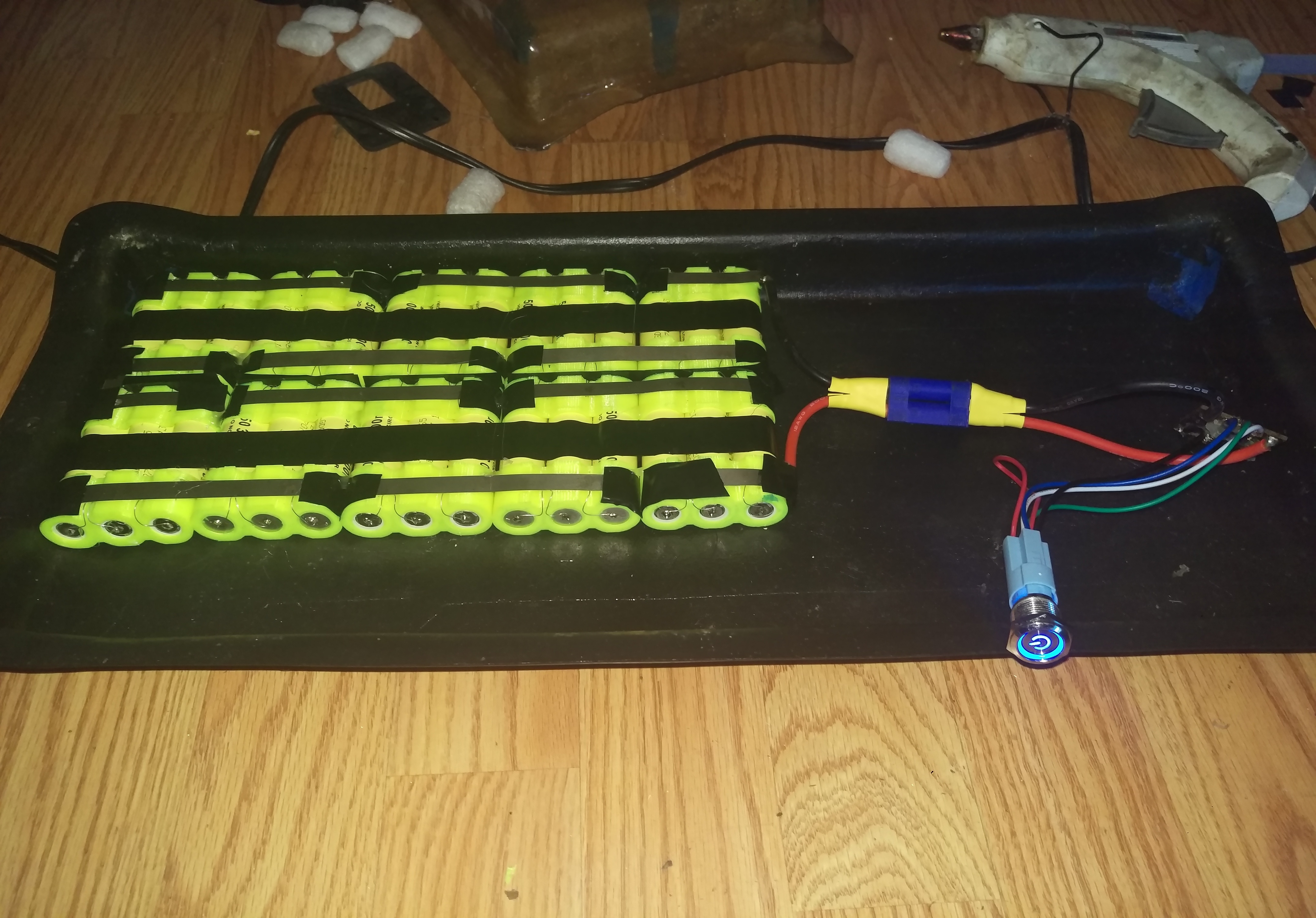
And this is how I wired my board with the led power switch. Coming from the led, the red wire is positive, and black is ground. The green wire is C (Closed). The white wire is NO (Normally Opened). The Blue wire is NC (Normally Closed). The red wire (Positive) has to be connected to the white wire (NO) either by soldering or just simply pushing its wire into the “NO” slot. The white wire (NO) is soldered to the slot directly below the In-Postive of the Vedder Anti-spark board. The green wire © is soldered into the middle slot. The blue wire (NC) is soldered into the slot above the In-Negative of anti-spark board. Lastly, the black wire (Negative) from the led is soldered into the Out-Negative of the anti-spark board. Hope that make sense…For me it did not work as expected when i have hold the cables against the pin. I did not solder it yet. For testing purpose…
Maybe i should just solder it on and report back thanks for the help!
So I saw this thread and got curious about getting the LED switch to work. I have no electrical and barely any soldering skills. I literally just got into the eboard scene 2 months ago. Totally new at all of this.
I started my first build and I really want an LED switch. So I tested on this cheap little guy today that I bought a while back https://www.amazon.com/gp/product/B01D2S6ZPK/ref=oh_aui_detailpage_o03_s00?ie=UTF8&psc=1. I wired it up and it works. The led light is really dim though. But it does function correctly and turns on and off as it should and also lights up. But as I said, the light is really dim. I ordered this one yesterday and it’s on the way https://www.amazon.com/gp/product/B00ZR7MMXO/ref=oh_aui_detailpage_o00_s00?ie=UTF8&psc=1
Do any of you know how to get the light to get as bright as it should? Does the positive need to go somewhere else to get ample power to the LED? Don’t mind the wiring. Nothing is color coded for now while testing. Any help at all would be appreciated.
Here’s a pic and video. For the video, everything was soldered up. You can see the the instant I press the power button it flashes bright really quick and then when it’s fully engaged it’s back to being very dim.

You don’t have it hooked up to a power source but just to the switch poles? 
To be honest… I don’t know? I’m literally winging everything. 
You have to connect the GND and +12V of the switch to the main cable pads behind the mosfets, together with a suitable resistor in line so that you adjust your battery voltage to the 12V used by the switch’s LED.
Which button is it ? can you post a link ?
https://www.amazon.com/gp/product/B01D2S6ZPK/ref=oh_aui_detailpage_o03_s00?ie=UTF8&psc=1
I think my vedder switch went out now. After my first charge up with my new build I turned it on and the board wouldn’t turn off. Now I can’t even get a regular rocker switch to work. Ugh…
If we dont want to change the design of the switch (by adding another trace(?) and a resistor) this would be the only solution atm:
Just attach the LED + and - to the PCB like this. But you need to add a 3k-4k (maybe 6.8k?)resistor in front of the LED + that you dont get the complete current of the battery.
@JdogAwesome did i understand you correctly?