So heres a topic I couldn’t find any information about. I found 2 videos on youtube that have some oversight, but the lack details I need:
Maybe someone who has install hall sensors before could chime in?
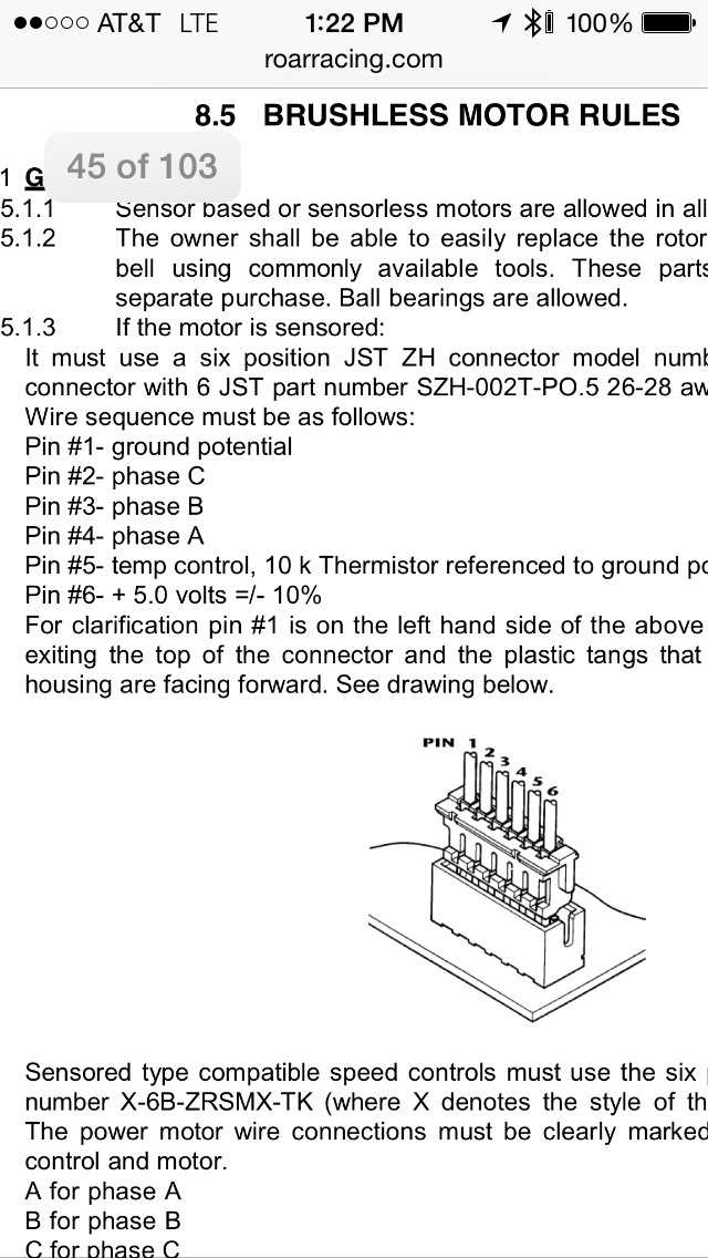
I’m mostly interested in the exact placement of the sensors and the configuration of the wires into the plug for the sensor. Not really sure where to start. Maybe someone with more knowledge could chime it? It would be nice to if with the help of the community, we could build a guide for the rest of community so that others like me who have no experience with hall sensors can sensor their motors.
What I’m confused about is my understanding was each hall sensor has a +, and -, and a control.
How far apart should they be placed? 120 degrees?
And how do I determine which one is A, B and C?
What is the temp control?
Do I combine all of the negatives and positives from the sensors together so they can connect to pin 1 and 6?
Which one is A, B, C is detected from the VESC automatically. You can wire the three output pins to the VESC H1, H2, H3 port how you want. GND and 5v are shared for the three hall sensors.
Temp control isn’t implemented in the VESC 4.x.
I used “external” hall sensors on my sk3 6374 motor for testing. You can find PCB files and 3D printing files here for an example: http://e0designs.com/products/hall-effect-sensor-board/
I had the problem that the PCB was so large, that it crashed to the skateboard deck when turning. But it definitely is a great upgrade.
I have purchased the EO Designs kit in the beginning but as @hexakopter said it adds some girth to the motor so I decided internal was the way to go. Both the diagram and the link helped me greatly to understand hall sensors.