So I’ve been using my first DIY for a while now and my settings have been sufficient for me. I tried being conservative with them because it’s my first build and I don’t want it to go up in flames, but I feel like I’m limiting myself and the board’s potential. My settings are:
Motor max: 80 (160 total)
Motor min: -60 (-120 total)
Batt max: 35 (70 total)
Batt min: -20 (-40 total)
Since my board is mostly a Kaly clone (Trampa with 8-in wheels) I followed his settings with a few tweaks (+20 motor amps, +5 batt amps)
I can’t remember the specs on these but I’m not that worried about it being a bottleneck.
I’m using 12awg wires connected to an antispark with an 80a fuse, then to an xt60 parallel harness.
On the motors side I’m using SK8 6374 motors with these specs:
Given the components that I’ve enumerated, should I keep my settings or push it more? Should I double down on the series nickel strips? Do I need more batt amps?
You can probably turn up your motors to 100/-80 without much impact on motor reliability, depending on how often and how long you gun it. Some people seem to set up their 6355, 150 Kv motors at 80A without problems, which means 6374 200 Kv motors should be good for 120A+. As long as your ESC thermal throttles itself if it stats overheating, I think its probably worth a shot.
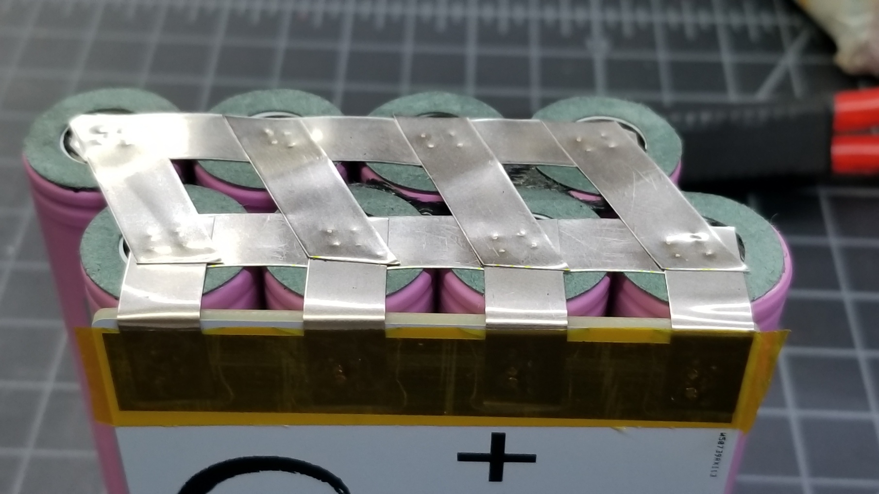
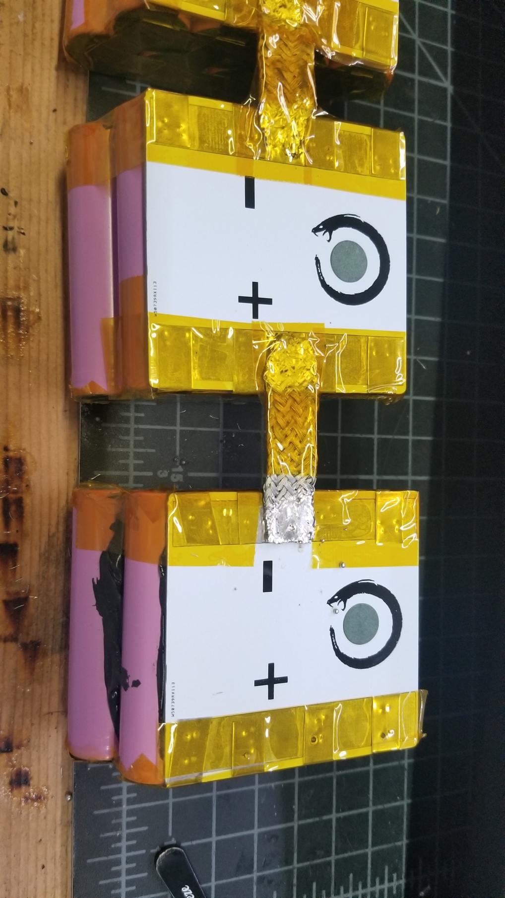
You should look into what the max current of your nickle strip and copper braid is. 8mm nickle is probably good for about 10A safely, and given the way you built the pack with only 4 strips connecting 8 cells to the bus bar for each parallel group, that limits you to only about 40A total. If thats the case, your 70A battery max is pretty concerning. It’d be pretty easy to double or triple up the connections though. I also dont know the current rating of that copper braid, but I suspect you might be close to its limits.
Definitely it looks like your wiring is the bottleneck. An 8p pack of 30Q cells can be run close to 160A, but only with appropriate wiring.
Whats your top speed btw, and are you actually hitting that speed very often? You might also consider shortening your gearing.
Ok, so you are all good with upping settings vesc wise but you do need to add some extra nickel to those battery parallel connections. Currently they are not up to even your current settings
If I were you I would immediately drop battery current to 32 A as a matter of safety
Your system has a lot of potential but is generally not well optimized for your particular use case. You are geared for speed instead of torque, but riding in a very hilly area (high torque) with crap roads (low speed). If you reconfigured some stuff, you could double your power and triple your torque. It would crush hills.
There’s three ways to go forward
enjoy it as it is, it’s already a lot of fun if not optimal
hire someone to reconfigure
educate yourself and DIY
if you go the latter route, you have to put in the work, few people have the time to spend a few hours spoon feeding everything, so it takes independent work. But luckily it’s not that complicated in the end, you can definitely do it. Your obviously quite capable, it’s an awesome looking build.
Except he doesn’t know what the current capacity of the nickel strips means. Lots of diy know how and common sense for sure, just a few gaps in physics here and there
That’s one of the big challenges of any diy endeavor. You often don’t know what you don’t know, and don’t know if you’re ready. We have to do our best to recognize when we’re out of our depth.
I thought I knew how to build a board and consider myself pretty technically savvy, but I’m still struggling to get reliable performance out of my build. Lately it’s over voltage errors, maybe a capacitor issue, maybe some loose sparking connections, maybe a bad esc… If I could pay someone a couple hundred dollars to guarantee a reliable device, I would. The know how is hard won.
I know what it means, I just don’t have any hard reference telling me how much amps a nickel strip can handle. Some people say 4a, some people say 10a. Some people say it changes depending on how long the strip is (not just thickness and width). I based my build off of a Kaly. I’m using the same PCB, same nickel strips, and close to the same vesc settings, just that I have twice the number of parallel cells:
So while I don’t have the hard numbers for the nickel strips, I do have a basis for saying that my battery and wiring can handle what I have currently.
That being said, I spun up this thread to see what other people have to say about my current setup. So any comments and suggestions are certainly welcome. That’s what being a community is about.
OK my bad I underestimated you. Sorry about that, dick move on my part.
Agreed, lots of conflicting reports on the ampacity. Worth doubling, even quadrupling up I think, assuming 5-7A per strip and 20A for 30Q’s (assuming you’re bypassing BMS). Kaly may be using 4x 8mm strips, but you are already at 110% the battery amps that he’s running, and have the lithium to get to over 200%. If it were me, I’d beef up those connections, and crank up all the current settings
I think a lot of people fail to recognize that one really doesn’t have to size all wiring to max ampacity. The amount of time your motors are actually drawing that kind of power is fairly minimal. That said if you built a machine to uphill race, then by all means beef the hell out of your wiring. But if you can crush most hills you’re climbing in under a minute, likely you won’t even heat up undersized wiring. The biggest spots where wiring is important is the series connections. Looks like your braided strips are going to do the trick just fine.
When electricians are determining wire size for feeders, they typically multiply ampacities by ‘service factor’. Meaning how long and often will the devices be used daily? So say 1200amps of load on a feeder, and a service factor of 0.4. They would determine wire size based on 480amps.
I wouldn’t typically mention this because too often we see batteries with insufficient series wiring, but in this case it looks fine.
TD;DR Y’all should be fine to beef up your settings. The wiring is fine.
Agreed. When I ride, especially when climbing a hill, I use the metr app to monitor my amp draw. At dead stop I for sure draw like 60+ amps but when I get going I can climb a fairly steep hill at 15-20mph with about 30-40 amps continuous.
You can see that I did a steady climb (green line graph) and when I get to speed (brown line graph) there are small amp draw spikes (red line graph) but it doesn’t really plateau anywhere close to 60 amps.