Hey guys! I finally got some time to get started on this. I will be posting pictures and info as i progress with the design and development.
For this iteration i went with what i had in hand (SS495A from honeywell), its rated 4.5V min, but for some reason it just works with the 3.3v the remote uses. I will change it for a 3.3v rated sensor later down the road, just for peace of mind more than anything else.
As for powering the remote, im using sparkfun’s powercell which can output 3.3v or 5v and a 1Ah lipo pack (again, what i had lying around)
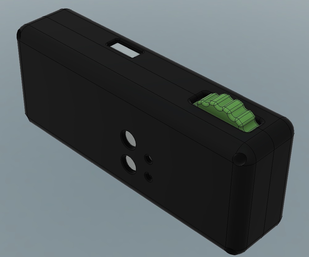
That, at the moment is just an arduino with an lcd. I dont want to design a new remote, i just want to mod the mini remote to something more user friendly.
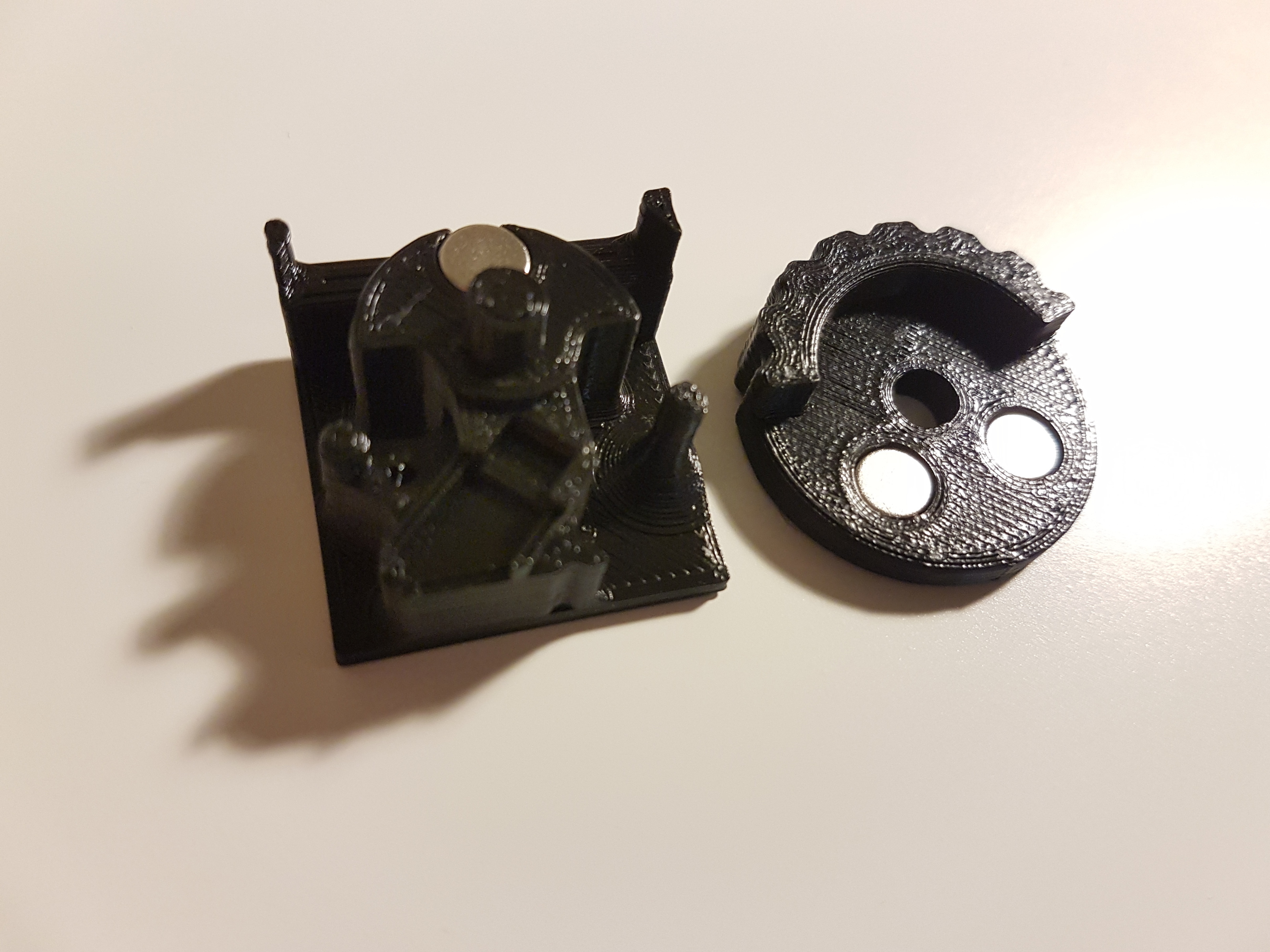
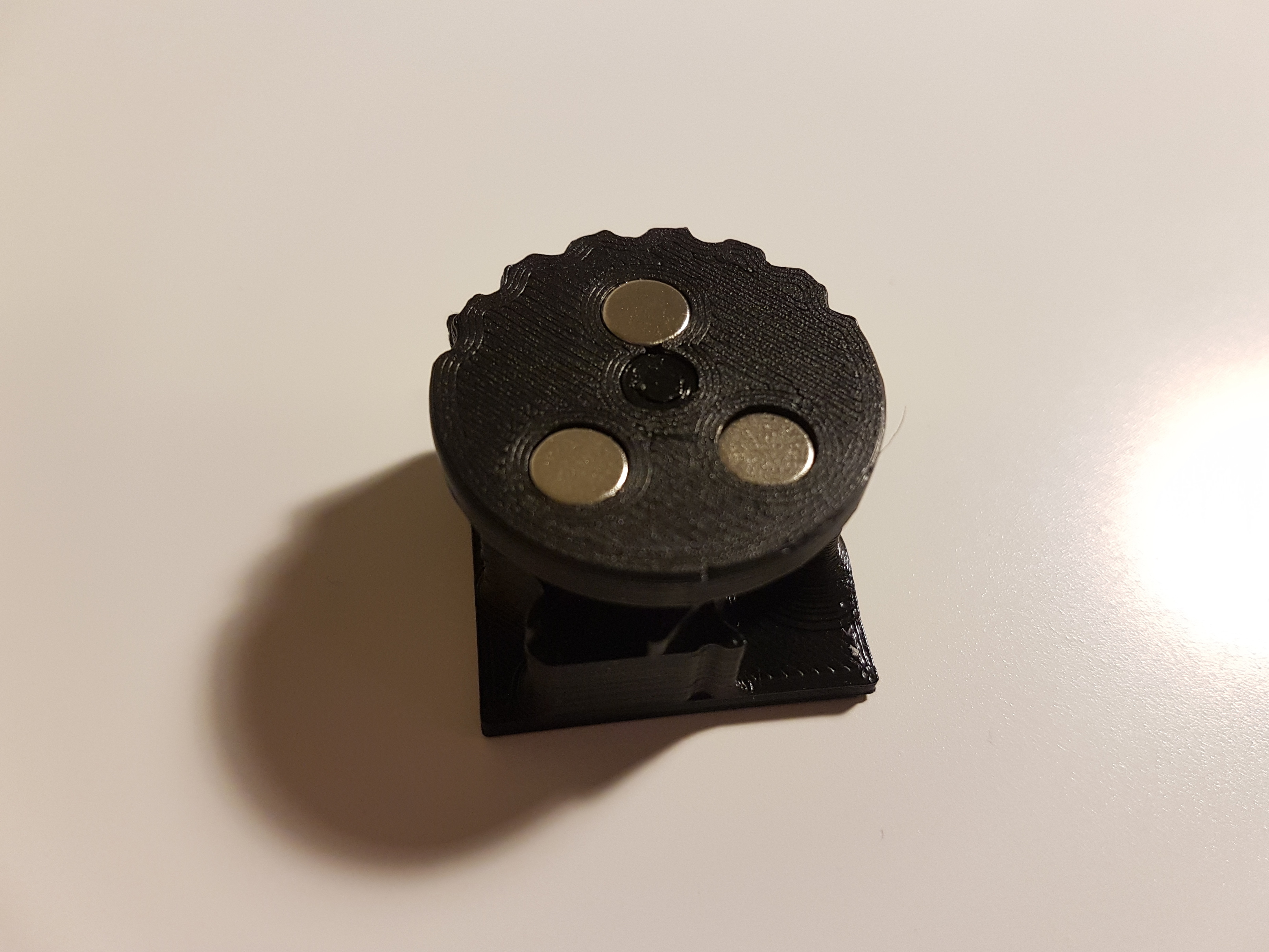
So, i’ve made quite a bit of progress! Everything seems to be working fine. I need to get some softer springs since just by coincidence, a screw sits right below a magnet and even without springs the wheel returns to center
I had to do some quick modifications for fitment, like cutting a slot for the sensor cables and a relief for the on/off switch. Already have the changes made to my design and will print new cases tomorrow!
Really nice. I got distracted from my mini remote mod but I have the same hallsensor working on a diy power glove + mini remote pcb.
I thought about doing the boosted wheel thing but i don’t have any springs and didnt want to rely on printed springs…
I have some more ergonomic designs that already have the pcb cutouts
this is what happens when you keep designing instead of just making a box that works
I saw thread! Haha, got a bit derailed!
At the moment im focusing on the functionality of the design rather than ergonomics (altough, it feels great in the hand). I’ve already added an index finger cutout so that it sits nicer.
On my next version i will probably rotate the thumbwheel assembly 45 degrees so that it matches how our thumb stays at rest (like boosted remote).
Im also planning on flipping the pcbs over so that the on/off switch is on the same side as the thumbwheel. The only problem is that i basically need to rebuild the whole design, its gotten too messy after so many tweaks haha!
@saul haha, yeah, that happens a lot, i usually keep old designs for a bit then just throw them away.
@Sarky1 It wouldn’t be tricky to do, since the way these remotes work cutting the return from the hall sensor would effectively set the remote to neutral.
I will be redoing the design for a more comfortable fit, and im thinking just using the same shape and thumbwheel design as boosted, so i can add a deadman’s switch to it as well.
I haven’t done any street testing yet, im still running the gt2b until i have some time to print new cases for this new revision. From what i’ve read here in the forum, the mini remote is as good as the gt2b. The only thing i can see that seems a bit crap is the on/off switch, its just a cheap one; Mine actually works when it wants to i have to solder a new one.
I’m having problems with this mod. I’m using the same remote and hall sensor just a different case but the concept is extacly like yours.
Everything worked fine for like 2 hrs but then something strange happened, it looked like the throttle stuck open, so the board would keep accelerating and i wasn’t able to brake nor going in neutral. at all.
I thought that could be a calibration issue, so i recalibrated my esc/remote and doing so it took a couple of tries because the esc wasn’t “sensing” the brakes, and again it worked fine for a couple of minutes, but then again, the same thing happened. I think it could be a sensor/remote issue since if I switch the remote off, the board goes to neutral.
Any idea of what the problem could be? it seems like the hall sensor get “polarised” like a magnet…
So it seems. Now when I try to calibrate it doesn’t recognize one of the magnetic poles on either side. When I get home I’ll measure the voltage drops… Unfortunately I don’t have spares atm. I’ll have to wait for them to arrive…


 Damn, that things awesome.