it does not matter to which screw you tighten the balance cable, they both are literally the same spot as far as the BMS can tell
1 Like
Was quicker to cad and have them inline. I think this is basic stuff electrically and all should know that it is the same where on conductor you place your connection, it will get connected 
I made a new enclosure for DieBieMS. It is a bit wider(5mm) than the standard NESE box and I have moved a few things around to attach the balance connectors while BMS is already mounted in place. It has more space for routing the balance wires and restricts them in a channel. The copper tabs are very easy to DIY now. Only one 90 degree bend.
Rest of the pics here. The pic below is a completely assembled working board.

5 Likes
Rear view
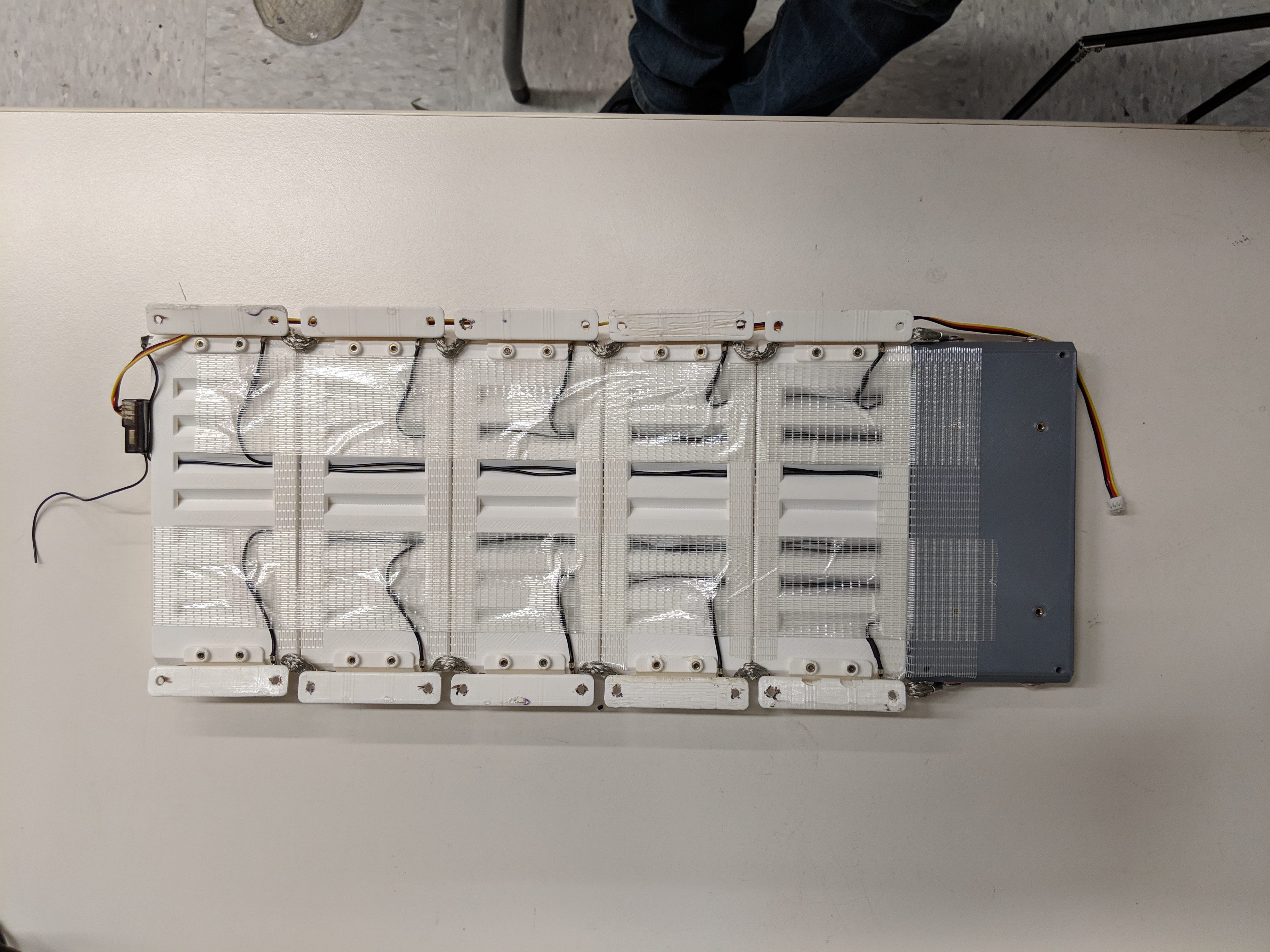
Front

10 Likes
Such a beauty!

3 Likes
So, i want to be grumpy  I had flames thrown at me for making some statements. Don’t want to tag Winfly here as i don’t want to put him off of hes development endeavour.
Will quote hes first post:
1. Cost
_ * It’s kind of expensive. €103.35 for a 10s4p module to ship to the US_
2. Size
_ * it got that extended part for screws terminals. I don’t see it as a necessity. It adds length to the whole P group and IMO length is pretty important since most battery packs are made laying the 18650s along the length of the deck_
I had flames thrown at me for making some statements. Don’t want to tag Winfly here as i don’t want to put him off of hes development endeavour.
Will quote hes first post:
1. Cost
_ * It’s kind of expensive. €103.35 for a 10s4p module to ship to the US_
2. Size
_ * it got that extended part for screws terminals. I don’t see it as a necessity. It adds length to the whole P group and IMO length is pretty important since most battery packs are made laying the 18650s along the length of the deck_
So the cost: 100USD NESE vs 80USD Winfly (and this is early access which most of the time is cheaper than regular) 20USD for stamped proper tab with raised nipple, plated, then proper low set foam for compression added must be worth that? What got me is that he even does not want to share stl files, not to mention CAD’s cause its bad for business. In the end, the system started taking NESE shape with lower quality components costing marginally less. Maybe its me but it does not make sense to me, and i was flamed for the things i said that became true in the end. Am i weird?
On the better note, my system is going to be used in student formula E. Pakistan team will be using it.
We were working on implementing temp sensors. Rules require to have one probe per 3 cells max with proximity of <10mm. I have found the sensor and implemented in NESE 8P module. it got wider by 3mm but is still compacts for car: (Illustration, middle probe is placed correctly now) Its not public, but if someone has project requiring this capability, its available on request (stl or cad)


9 Likes
The integrated temperature sensor looks fantastic. Congratulations that your system is going to be used by the Formula E Team.
My next battery pack will be a slightly modified version of your thin profile module with some easy way to pass the balance data from one module to the next in a modular way and finally into the DieBieMS/other BMS along with thermistors per cell pack.
Don’t be grumpy, you have a great tested product. I love the modularity, the safety, use of big m5 bolts for joining connections … Even though these modules look good on paper, when it comes to more people adopting it, well, they will need to see several different implementations that has been tested in real world condition for 1000s of miles(collectively). What would really help is for you(and other existing users) to assemble and showcase their functioning system. That would instil the confidence required and give users ideas to put together their system. To put that in a different way, understand that a lot of the experienced builders just use welded cells because they can make very compact system and a lot of the newer builders are afraid to try NESE because they don’t see a lot of builds based on that here(esk8 forum). You have a huge potential customer base but they need a bit of hand holding.
2 Likes
Funny is, a lot of these are in the wild. I mean a LOT. But I see one or two builds. Then I gathered if people do not talk about them, that’s a good thing, most of the time people start talking and looking for solutions when something does not work or have overall bad experience. Sadly all the good comments and thanks I get by email so no point in sharing as it might seem fake
1 Like
Another thing I wanted to share is I am engineering some stuff for the printer. The major thing is automation. I have two inexpensive ideas to try. One is nearing test phase with conveyor part removal. This allows unlimited parts to me manufactured unattended autonomously.
Here is most recent photo
 Another approach is using al2o3 porous ceramic plate with vacuum to hold parts while printing and then push them from build surface with lever. I am skeptical about this one as surface at the start of a print is very small for vacuum to work vut you never know. Needs to be tested.
If any of the solution will work, I will be able to cut my prices by further 10%.
Another approach is using al2o3 porous ceramic plate with vacuum to hold parts while printing and then push them from build surface with lever. I am skeptical about this one as surface at the start of a print is very small for vacuum to work vut you never know. Needs to be tested.
If any of the solution will work, I will be able to cut my prices by further 10%.
7 Likes
Well then one idea would be to encourage them(people saying thank you) to share a pic of their setup(on this thread or email them to you) and then you can put those pics here or on your web page, with their permission of course. You should def do that. Make different categories for their application and post pics under them.
Conveyor seems to be the easiest to implement. Also i am skeptical about the vacuum because it won’t let the bed heat up. Are you going to use tool steel plate for the conveyor, that is fed through certain distance using a servo?
If vacuum holds, then there is no need for heat, after all heat is used to get prints to stick. Conveyor will have a belt on top of aluminium heated platform. After print is finished, stepper motor will turn the conveyor and drop the part into collection bin. The another part will start and so on. I have 0.05mm stainless scheet to test as well as 0.25mm single layer carbon.

3 Likes
Have you seen the endless Y axis design? It uses a rolling bed very innovative Edit: you have indeed!
Any chance that you would look into cell level fusing at some stage? A mod to the case design and the cutting of tabs is all that is required.
Also/or some balance wire conduit/passage where they are safe from a short. That’s nice work with the Fomula E car, this is useful to the above ^
1 Like
Yes, the blackbelt. Its good for long parts but smaller does not look too good when printed. I have not seen such printer producing same quality parts as conventional printers and you are constrained how you orient parts. You get away with some overhangs but there is the other side to it.
1 Like
the moment i read conveyor belt i thought “Factorio”. Congrats on the cooperation with Formula E. Great stuff, love the new lower profile.
@agniusm, can this is printed without support? What settings do you recommend. I realize it varies between different printer setup but it will give me an idea.
Sorry but what? If you are talking about NESE, they are designed to be printed without supports as is
My question was about your slim file.
Sorry but no. I have not changed my mind on this. Having read formula e rules, there is no requirement and their regulations are strict. Its a complexity over nothing. I see why you would want that on second life cell in your house.
Its possible. You can make the nipple as wide as the cell, add proper fr4 gasket to positive of the cell and drill out the nipple so it sits on cell positive side negative edge. Than just solder or weld your fuse wire.
OK, if you dont mind soldering, can assemble 10k of orders, i can do it, and it will cost same as the usual tab 
2 Likes