so I have recreated this but it doesnt seem to work when i put in the xt90
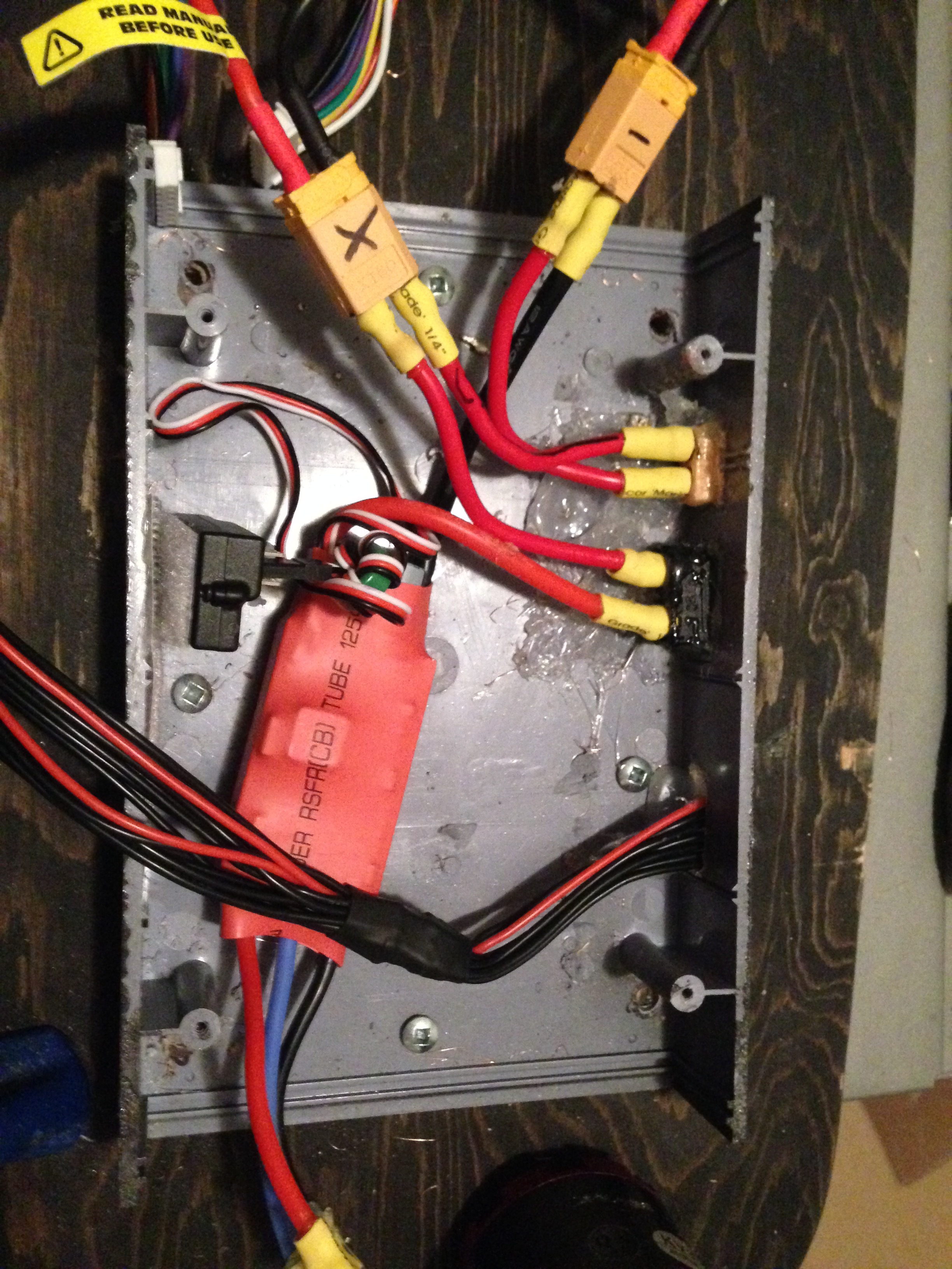
Here is what ive done
- Do you have a multi-meter? I would check voltages at every point to make sure there’s no breaks anywhere.
- I’m assuming the top port on the right side is charging and the bottom is the cutoff switch?
- Is the cut of switch an anti spark plug, or a button?
- Did you make sure you plugged it in/switched it on?
- Can we get a picture with the batteries in view?
I have used the multimeter everything is connected but when I use it over the xt90 no voltage goes through it and 44 volts going through the xt60 (charging port). but when I connect the two balance ports of the batteries together with my adapter. The xt90 connector has 22.2 V and same with the xt60 (charging port). But it still does not turn on. My xt90 anti spark hasn’t arrived yet. and here are some more photos


Well there’s your problem You have 1 pair of wires labeld ‘+’ on the xt60 but its actually a + and - from 1 pack. Same goes for the one labled ‘-’. If you take a look at the diagram you can see that they have 2 of the same polarity wire going in parallel to the respective destinations.
Your VESC right now is receiving 2 positive connections.
oh no sorry don’t worry about my labeling but you can see the black wire from the Esc connects to the black wire on the battery in the third photo
Ah I see, it was hidden behind the other wire. Either way, You’re circuit is not complete because the two packs don’t connect in any way. Let me see if I can draft up a fix for you.
but the guy that made that schematic said his worked fine before and had no problems
Yea, but your setup isn’t hooked up according to the diagram, give me a minute.
your wires are not connected the same way as the pictures shows, yours go from one plug to the other in series, I guess that if you close the circuit on the poles of the black plug you will be able to read the voltage correctly on the xt90, also I don’t think you can keep the parallel circuit (charging circuit) close while using the main one (discharging circuit / series) , but I may be wrong
I think my wires are connected fine i just switch the xt60 and the xt90
I think this should do it. Switch the wires as shown. Black wire (circled green) goes to where the Red wire (circled red) should be, and vice versa.

will that still keep it in parallel?
see this diagram (edit: this is for 12s)

the one that you’re using doesn’t really shows the connections, then you can join the xt60s and the balance leads in parallel
Yes, though 1 more change you need to do is short the connections on the XT60, it’d be easier if you just scrapped the XT60’s and soldered the wires together instead.
are you sure because i want to be able to remove them just in case and not have to solder them out
i see but that is in series
Yea, I’m pretty sure, but like I said the XT60’s have to either be shorted, or removed altogether.
oh you want 6S in parallel? I thought you wanted 12S, than that’s easier
okay I will do this change tomorrow and I will let you know how it goes. Thank you so much btw
thank you for your help anyways