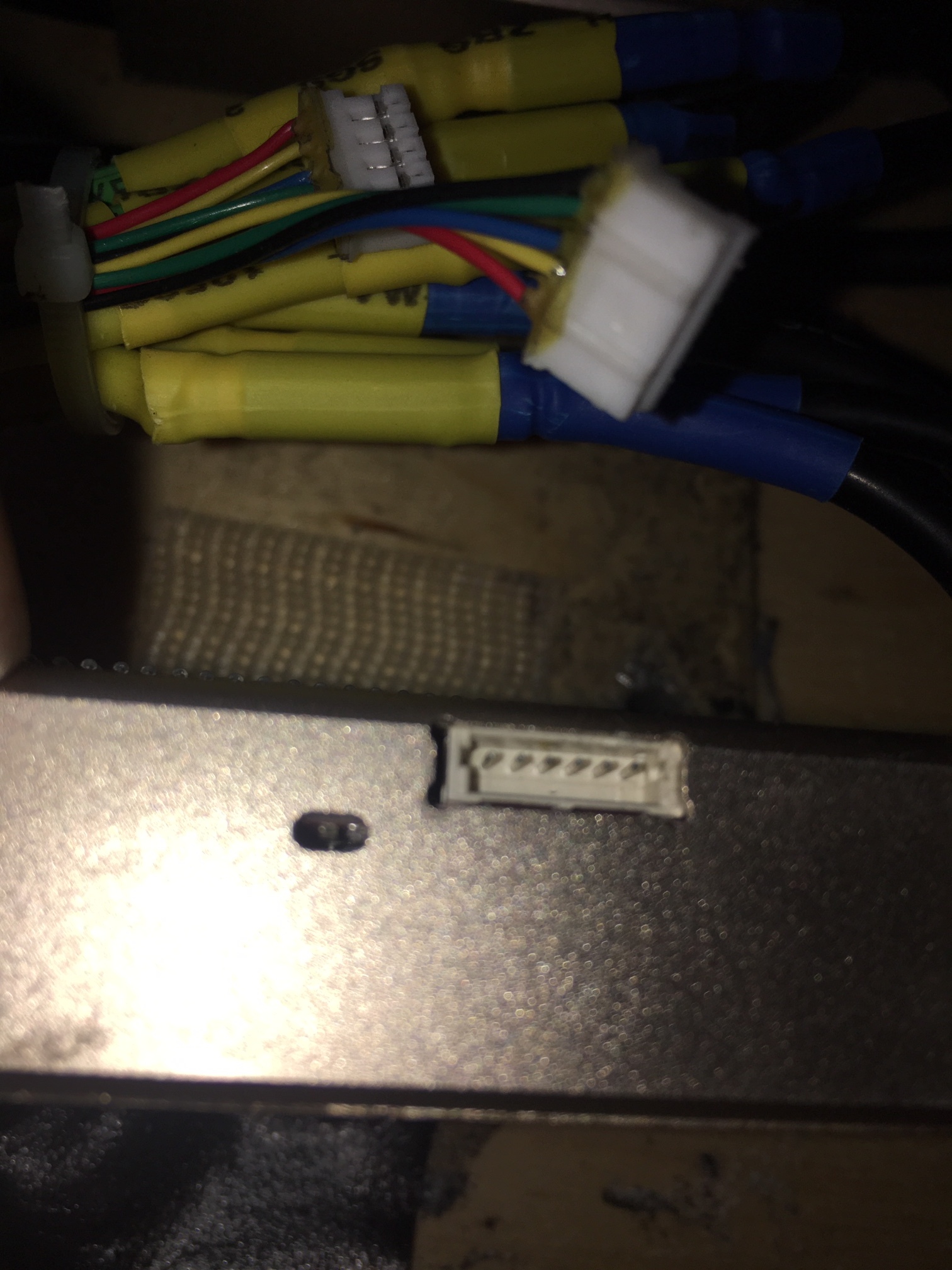
So I’d like to replace the male sensor pieces from my hub motors (5pinJST) to 6pinJST so that they fit into these FVT sleeping Lions. First off, is this even possible?
The problem, as you can see, is that the 6pinJST I want to solder on is not color coded and I have no idea which phases would go where. From what I’ve read I would just not solder the temp wire (the extra wire out of the 6/5) but I have no idea which wire is temp here. They are all black…What do I do??
So just to map out the purpose of this experiment - how am I using the numbers I get in my readings for each of these 5 pins to figure out my soldering situation?
Would I also take the 6pin JST, plug it into the VESC, and then get the readings of the 6 pins from there and then compare the readings across both JST’s?
Nah you just need to find anywhere negative on the same circuit, preferably close to where you are measuring. there’s gotta be somewhere you can stick it i would measure all of them and take note of them and try to figure out which is tthe temp sensor fron the readings.
I dont know what im talking about btw, just suggesting the course of action I would take


 i would measure all of them and take note of them and try to figure out which is tthe temp sensor fron the readings.