As a recap, a buddy and myself have been attempting to program a VESC V7 PCB with an ST Link V2 bought from a nearby mouser. We have tried probably about 4 different sessions each with ultimately the same result, but different errors along the way. Here’s what I have so far…
clip@Clip:~$ sudo apt-get install gcc-arm-none-eabi=4.9.3.2015q2-1trusty1
Reading package lists… Done
Building dependency tree
Reading state information… Done
E: Version ‘4.9.3.2015q2-1trusty1’ for ‘gcc-arm-none-eabi’ was not found
Followed instructions regarding toolchain compile for firmware. always have issues with the gcc-arm-none-eabi=4.9.3.2015q2-1trusty13 or trusty14
I went through and cleaned out the repositories that involved gcc-arm-none-eabi=4.9.3.2015q2-1trusty13 and friends. I will be trying again this evening, however I would love to hear some input as to how I could be mucking this up so terribly. I know it’s very simple and a few times I have gotten it to connect, albiet “Connected, limited”.
Alright, I think the dependencies problem is resolved. However, I think the problem now lies in the make upload for compiling the firmware onto the ESC. I reach this line of coding…
clip@clip:~/BLDC/bldc-firmware$ make upload
#qstlink2 --cli --erase --write build/BLDC_4_ChibiOS.bin
openocd -f interface/stlink-v2.cfg -c “set WORKAREASIZE 0x2000” -f target/stm32f4x_stlink.cfg -c “program build/BLDC_4_ChibiOS.elf verify reset”
Open On-Chip Debugger 0.7.0 (2013-10-22-08:31)
Licensed under GNU GPL v2
For bug reports, read
http://openocd.sourceforge.net/doc/doxygen/bugs.html
0x2000
Info : This adapter doesn’t support configurable speed
Info : STLINK v2 JTAG v23 API v2 SWIM v4 VID 0x0483 PID 0x3748
Info : Target voltage: 0.000000
Error: target voltage may be too low for reliable debugging
Error: init mode failed
in procedure ‘transport’
** OpenOCD init Failed **
shutdown command invoked
#openocd -f board/stm32f4discovery.cfg -c “reset_config trst_only combined” -c “program build/BLDC_4_ChibiOS.elf verify reset” # For openocd 0.9
Does this mean my programmer is incorrectly setup? Or is it the fault of the programmer itself.
Maybe a stupid question, but did you setup your ST-Link like this:
wget vedder.se/Temp/49-stlinkv2.rules
sudo mv 49-stlinkv2.rules /etc/udev/rules.d/
sudo reload udev
I’m getting the “configurable speed” message too, but then it uploads the firmware anyway.
Are you sure that all the Pins of the ST-Link and the VESC are connected the right way?
I saw a post on Vedder’s site that said you can use the 4 pin to get the job done… however I am not sure if the cabling is botched. Thanks again for your help.
What does it mean when you say this, Are you trying to put on different updated firmware? what version?
The VESC came with firmware preloaded when you first got it were you able to connect it to the BLDC tool and give it a try? Could you run motor detection? Or did you try loading new firmware immediately?
the code you posted means nothing to me I am not a programmer.
Well if you have don’t the latest pull from GitHub first thing you have to do is set the correct hardware as you can’t load the wrong firmware that isn’t made for that hardware atm I think Vedder has it set for HW 4.8 as default.
To do this go to BLDC/bldc-firmware/conf_general.g
Open conf_general.g in text editor and scroll down till you see a list some thing like this
make sure that this line is uncommented #define HW_VERSION_47
By uncommented remove the // like the 4.8 is above
And put // back in front of the one that didn’t have it.
save. Delete the build folder then do make upload again.
This might not fix your problem but it’s needed or you will have more problems.
Please are u using a VM? If so is the USB device connected to Ubuntu?
Try to type dsmeg into terminal and then look for stlink, it could be your windows portion won’t let go or doesn’t have drivers. It will one up with the errors you have if there is no device present to write to, the configurable speed will always show with it connected or not.
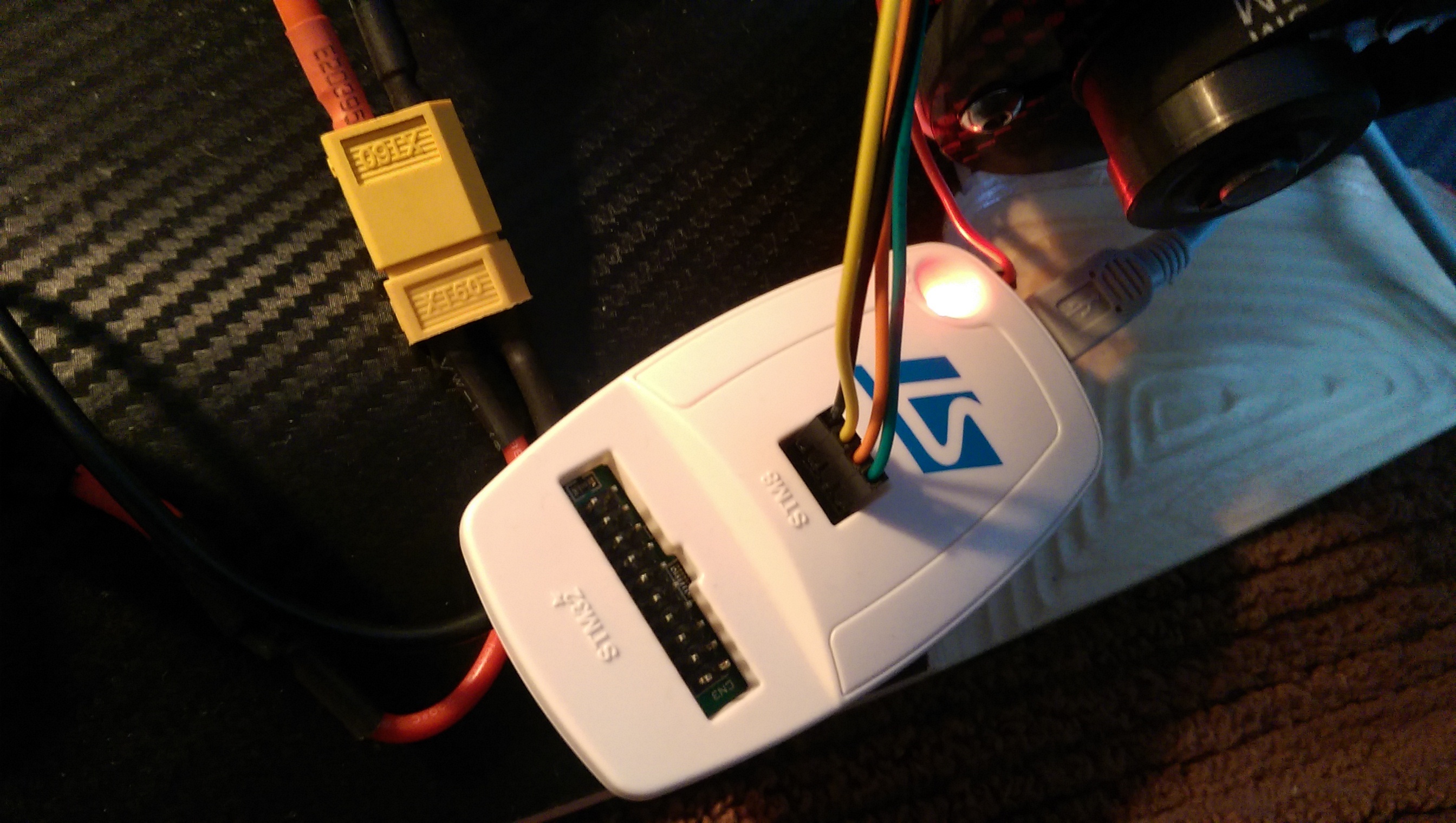
ALSO< i not sure if this matters, but the five wires/pins in the white connector sort of look like they are touching against each other? are the terminal pins for that connector meant to be like that?
May i know what is the exact hardware required for it?
What electric or electronics components you are using?
Which type of motors i can use and what are their drivers?
Also which MCU is used for it?