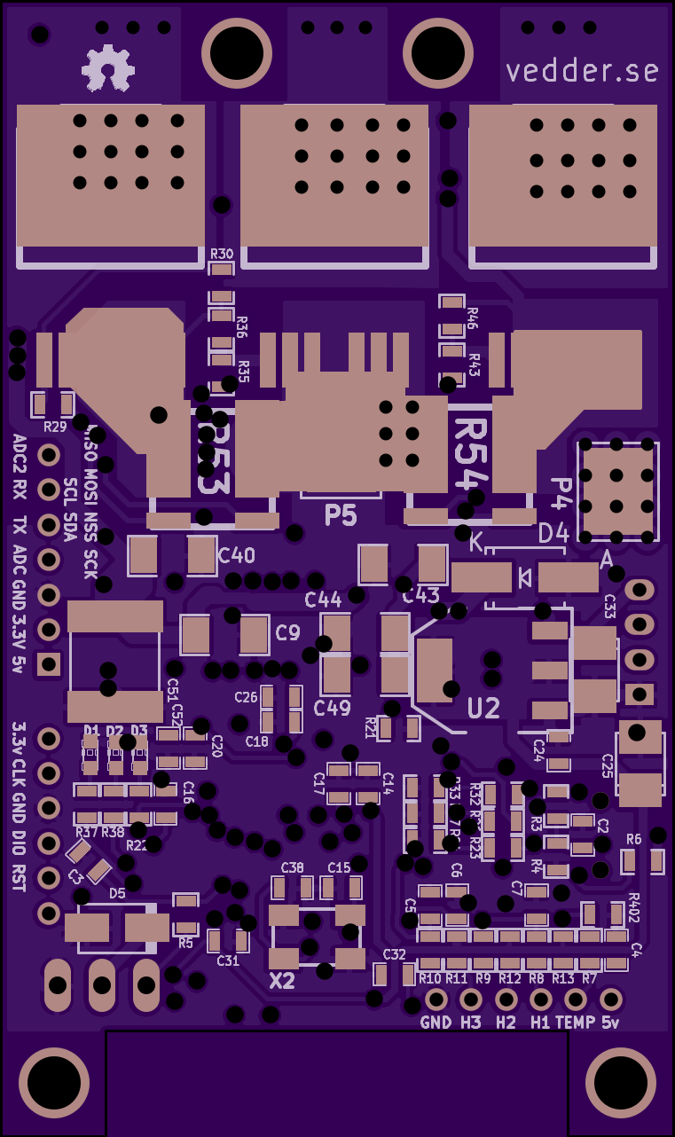
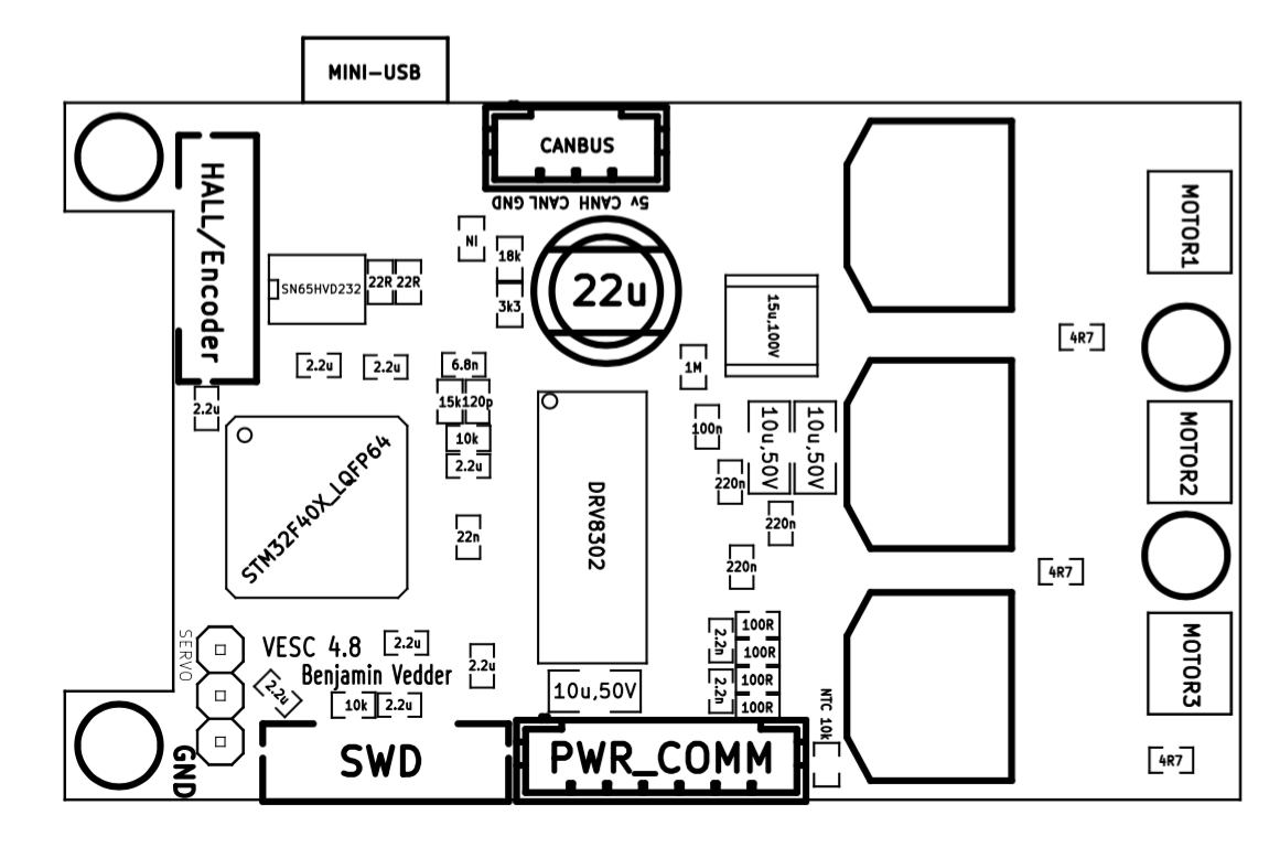
I believe I put it so the text on the chip was right side from how you have the PCB oriented in the picture above, but the truth is that it doesn’t matter. Given the orientation of the crystal I am almost positive it will work either way (just not upside down) since it’s a crystal that just oscillates (doesn’t have polarity) and the grounds are in opposite corners. I can check it in the morning for you to be sure, if no one beats me to it. edit: The spec sheet (found via Mouser here indicates that usually pad 1 has a slight chamfer (think “cut corner”), on the inside, as you can see in this screenshot from the spec sheet.
Pad 1 is the one that goes in top right of the board in the orientation of the pictures you posted (the closest pad to C5)
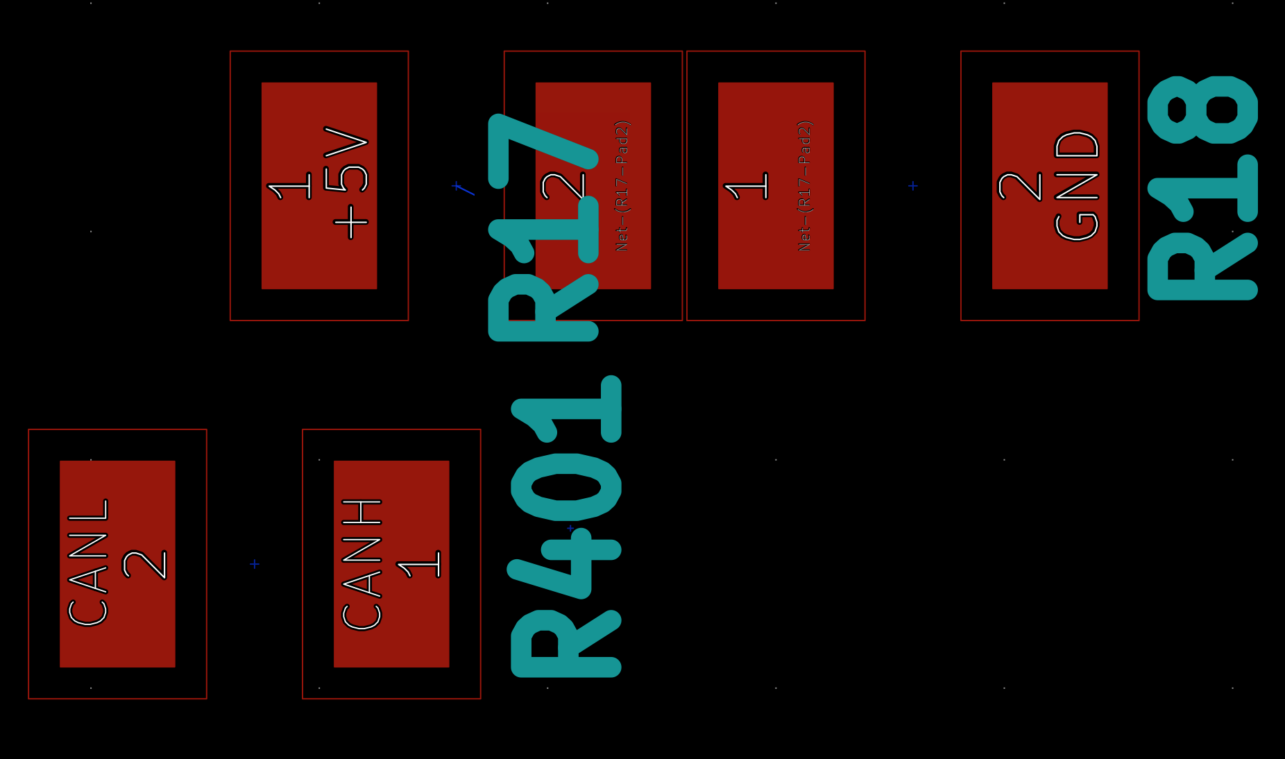
Gnd is up. Here’s a screenshot I just took from Vedder’s schematics. Just note that it shows them in the mirror as you see them (D1 to D3 right to left, instead of left to right as is seen from that side of the board) .
Tried to check what I did, but I can’t see through my shrink wrap and behind my red wire…but I’m still fairly confident that it doesn’t matter, just as @JohnnyMeduse said.
To flash the VESC with the bootloader and default firmware I used Windows 10. I think the stlink software I found first ran on windows, so I wen with it, but I’ve done stuff since with Linux. I flashed my nunchuckrf in ubuntu.
Ok thanks, then maybe you can help me.
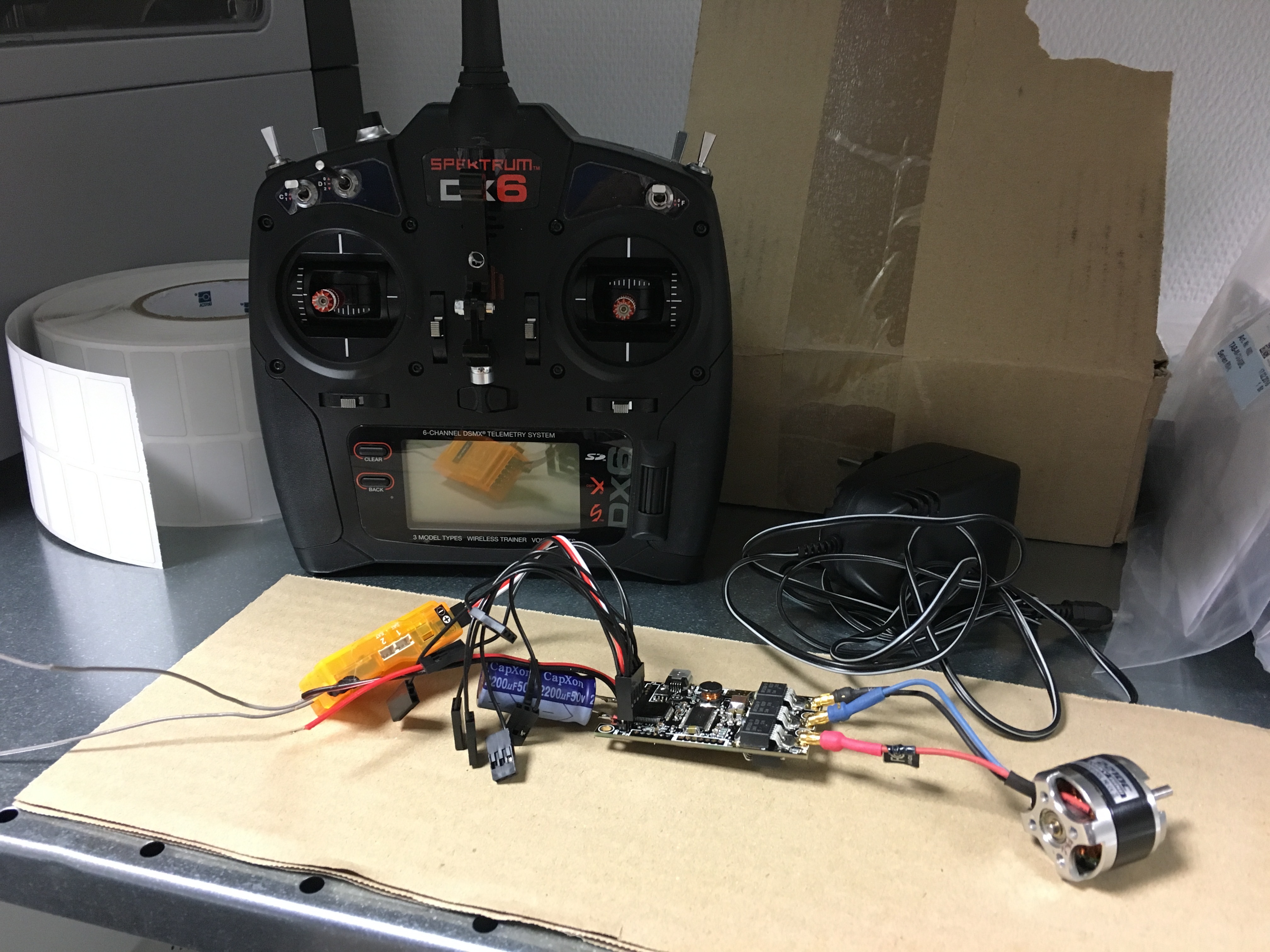
I have the ST-Link2 the withe one.
And I also want to flash with windows.
But I don’t know where I can get the hex file for the 4.12.
And also someone said I need 2 hex files one for the software and one for the bootloader.
Other ones said there is a single hex file with both.
How do you do it?
And can you maybe upload the hex?
Or give me a link ?
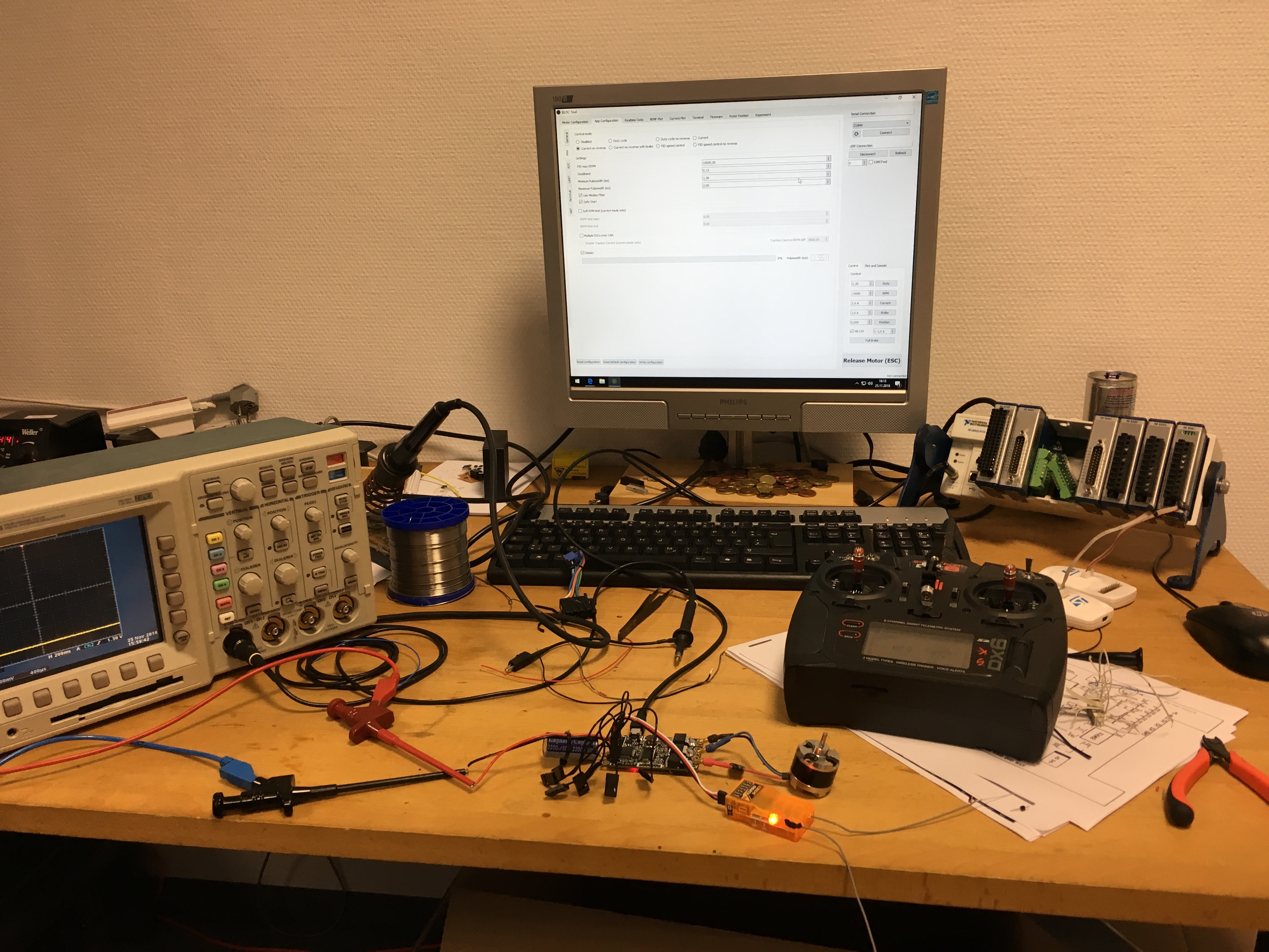
Today I tried to connect the controller and tried to program it.
But it doesn’t work
I measured some things and saw that the power input of the programer was not 3.3 V It was 1.5 V
Also there was no high signal on reset pin while programming.
And I know that the ST link is fine because I programmed some other electronics with it
What can I do next?
And If i did not get it will someone buy the VESC from me? Otherwise it will lay around years
Or maybe could check the problem? I would buy for it…
(I am from Germany)
My job is electronics and i have equipment.
So if u have an advice what to measure I can do it with oscilloscope e.g.
Did you find the hex file? I think there’s some with the bootloader (to allow to flash over USB in the future) and some without. At the bottom of that video, he has this link to hex files: http://vesc.net.au/flash/
Just double check after flashing if they have the current ramp bug, cause I think they might…and it’ll fry your drv. If it does have it, just reflash with the USB to a known good ones (no need for hex now, since the bug isn’t in the bootloader). That’s pretty much what happened to me, but I fried my DRV before I found it cause I was stupid and didn’t check after flashing.
You don’t see a light on the VESC do you? The blue light should come on if I remember…
But I have one more question…
Is it normal that I got misfires with that little BL-Motor? 2000kv or sth.
I only had that one around and tested it with it.
And when I give throttle the motor stops at highspeed. Then won’t move. First I must go back to zero then I can throttle up again.
What could that be? Or do you think it’s only because this little motor is too fast?


 I measured some things and saw that the power input of the programer was not 3.3 V It was 1.5 V
Also there was no high signal on reset pin while programming.
I measured some things and saw that the power input of the programer was not 3.3 V It was 1.5 V
Also there was no high signal on reset pin while programming.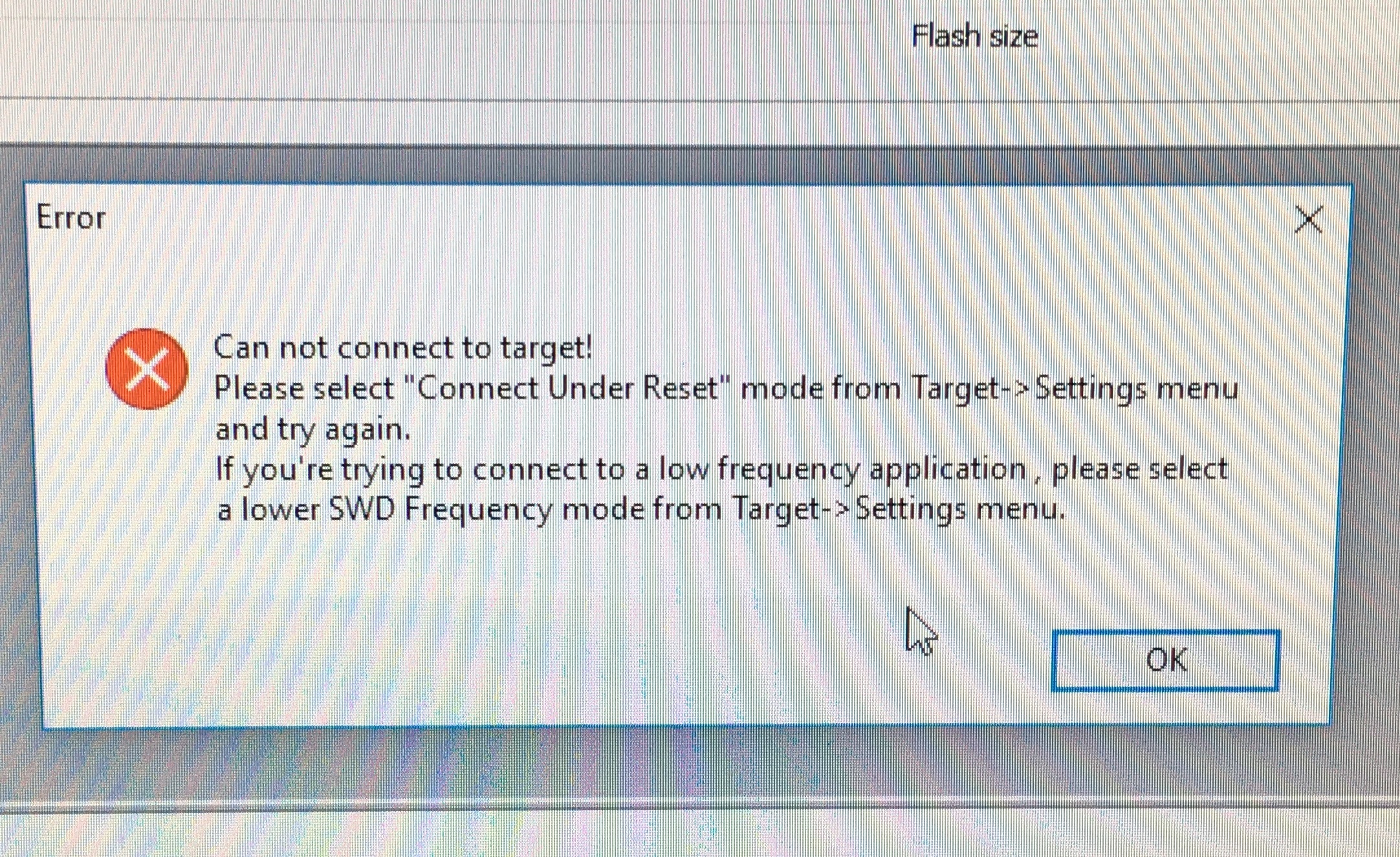
 Or maybe could check the problem? I would buy for it…
(I am from Germany)
Or maybe could check the problem? I would buy for it…
(I am from Germany)