First of all, thanks to the grabcad folks who posted up the wheel, bearing, truck and motor designs freely to use in my renders as references! Links to sources/authors for those soon…
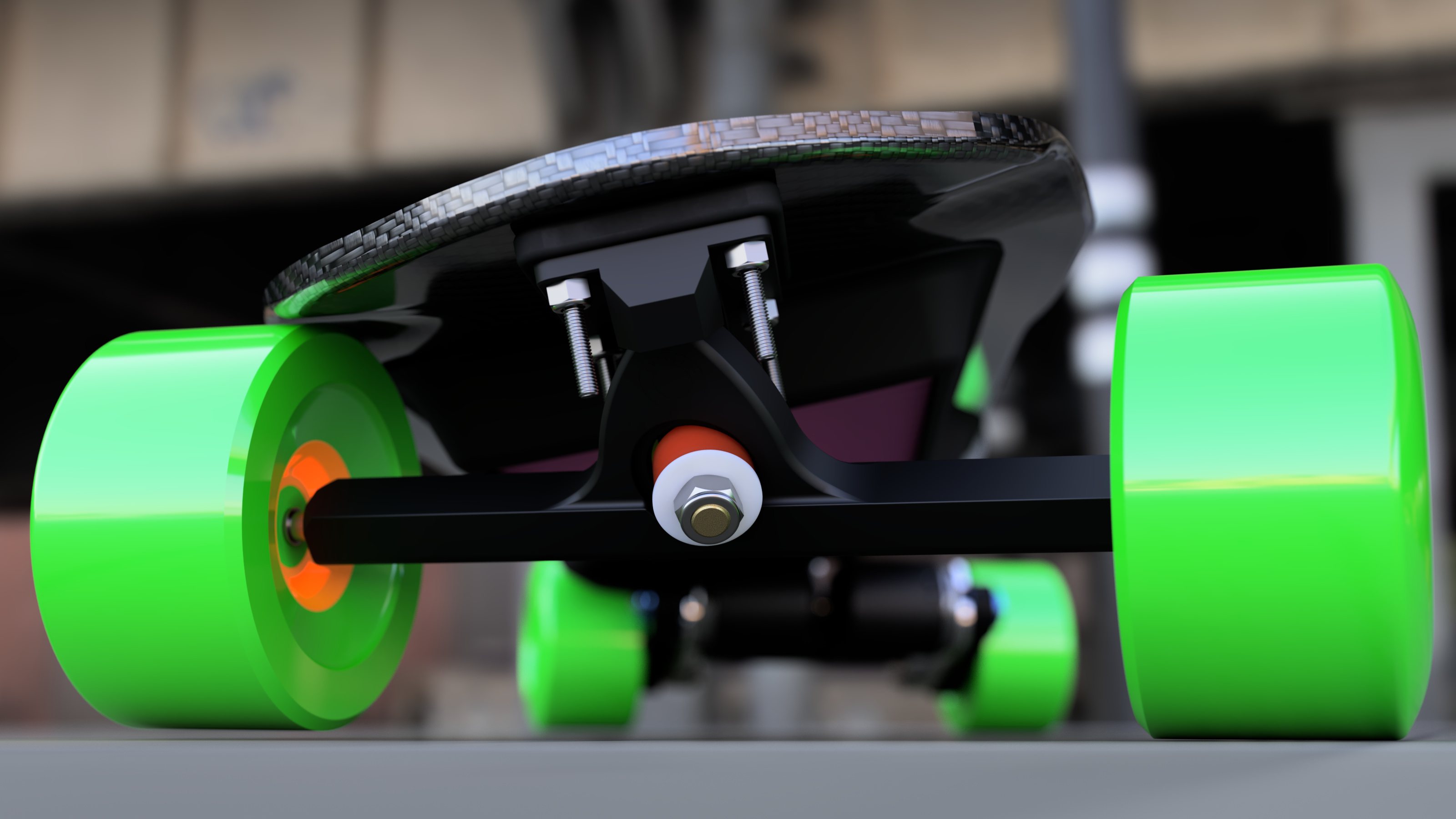
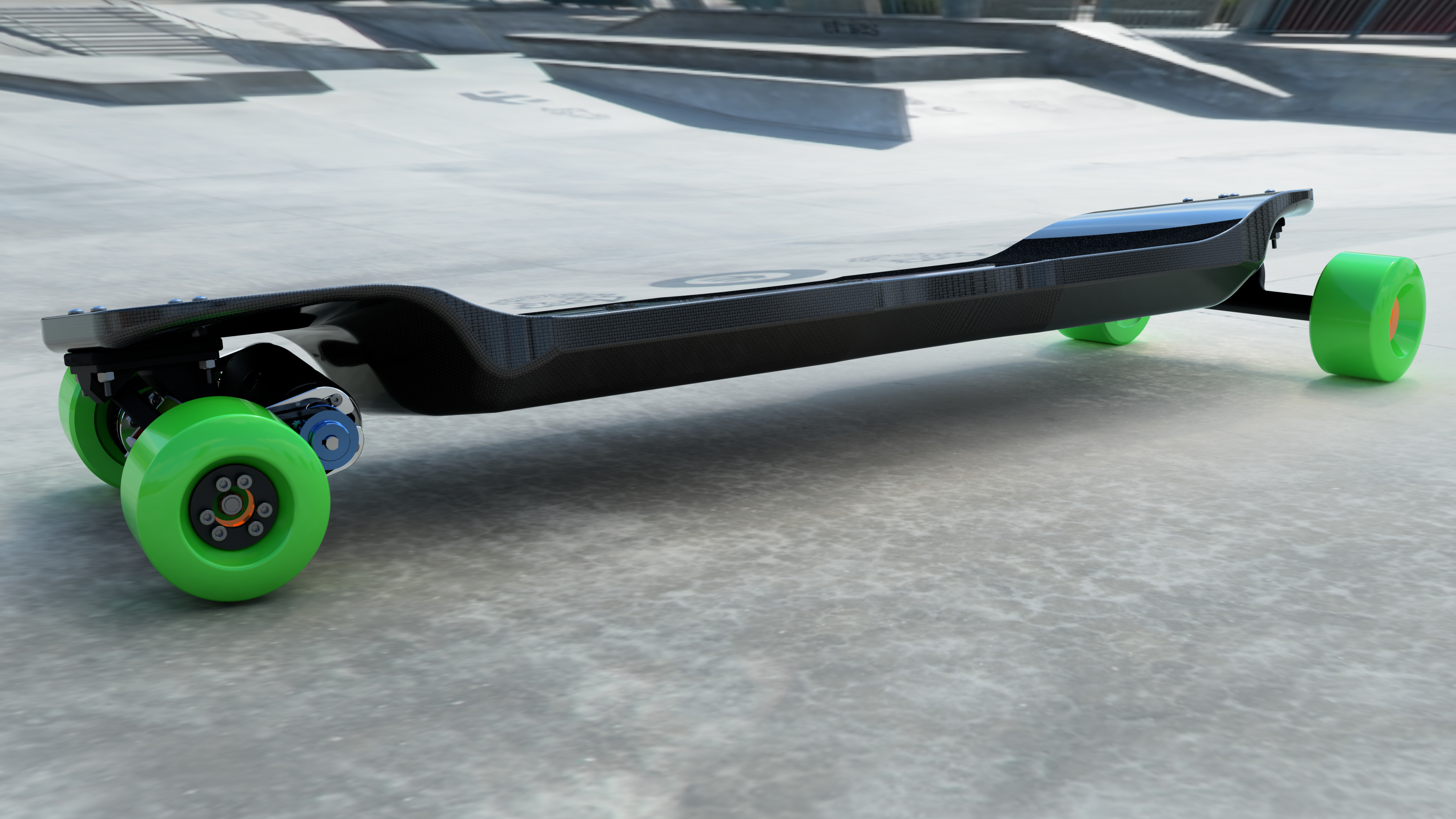
The meat and potatoes of this post will be the renders, but I have a few questions. First of all, this is my second mockup of an integrated deck, after first trying out a top-mount no drop deck, but upon suggestion by some members of my local ride group, I came to the conclusion that it would be too high so I went for a drop down. Before I get on with the questions here’s one pic to get you all started:
I am looking into pushing forward into turning this into something manufactureable. I know @onloop probably has experience with carbon fiber vacuum forming, which is what I have the most questions for myself on how to make this come to life. I have experience press forming my own maple longboard decks, but I want to take this one to the next level, and in my experience, 3 ply maple veneer sandwiching a foam core wrapped in CF equals a super lightweight board for the size and feels like riding on clouds.
Here are some of my thoughts so far:
-
If anyone has a good name for this, feel free… I am not creative with names and I would end up calling it the integrated concept board and leave it at that.
-
For manufacturing, I have had a couple ideas. This thread will be of some help in this process… thanks @Dornacht!:
-
Just form the top and bottom shapes out of 3d printed parts for precision, and make a jig for pressing all the layers together and having the wheel wells, battery / esc housing, etc CNC cut for precision. This would probably be the easiest of all, but also the heaviest.
-
press forming the top 3 layers out of a jig, like above, but just as the initial top layer veneer, and have the battery cutout laser cut or CNC routed. Then, CNC cut the foam core (in however many pieces) to layup ontop of and seal to the veneer in a vacuum bag. Thirdly, layup in a press the bottom 3 layers of maple veneer, have it cut. Finally, apply they bottom layer veneer to the bottom of the top veneer/foamcore layup and wrap it all in CF to vacuum seal it all together.
- Cable routing channels will be a challenge / are a challenge I haven’t come up with a solution for yet, but I am thinking something along the lines of having holes cut through from the battery compartment to just under the truck through the deck on the foam sections. During the CF final layup, instead of trying to fill the inside of those channels with CF (which I don’t think the inside of those channels will end up properly vacuum formed to the inside of the channels), is to design some sort of 3D printed (nylon maybe, epoxy sealed for air-tightness) capped (but easily removable caps) that I can insert into the final layup prior to CF vacuum forming, that I can rout out into the channels at the end to expose the insides of the channels to run the cables through. If anyone else has any better ideas, I am open to suggestions.
-
Other Misc: Another route I am considering but leaning away from is 3D printing a full size scale model of the outer dimensions of the deck, constructing a large silicone mold of the smoothed model, and injecting some compatible liquid expansion foam directly into the mold after placing pressed top / bottom veneers and enclosure structures in place, and letting the foam fill all the outer gaps, and finally wrapping and forming the CF around that. I’ve come up with a few other variations and combinations of the past two ideas other than this, that I won’t try to go into too much detail here… but if anyone with experience with this kind of stuff has any suggestions for improvements or ideas for another way to go about this, please let me know as I am about to get to the heavy youtube / tutorial stage and would like to start buying supplies at some point (not too soon though).
-
.5 I know I need to model in probably another 1.5mm gap between the top of the enclosure and the deck itself to account for probably a laser cut rubber or neoprene sheet to act as a seal between the enclosure cover and the deck.
-
.5 .5 I have also considered 3D printing a nylon enclosure shell (just the structure for the inside of the enclosure, maybe 3-5mm thick), or milling out of pressed maple just the shell, because I need to integrate m3 threaded inserts for the screws that hold the cover down into. No way can I just screw the lid into wood or worse yet foamcore- it probably won’t hold and I don’t want this janky.
-
For the enclosure lid, I’ll probably just press and planar cut the flat bottom portion out of maple and layer with CF on top, or maybe vacuum form CF on milled foamcore for that too with extra CF for the screw hole areas. not sure.
In summary… there are still a lot of unknowns here for me and I’d just like the get the communities input, thoughts, ideas, etc. Now, before the rest of the renders, i’ll just go into some of the basic specs this board was designed around:
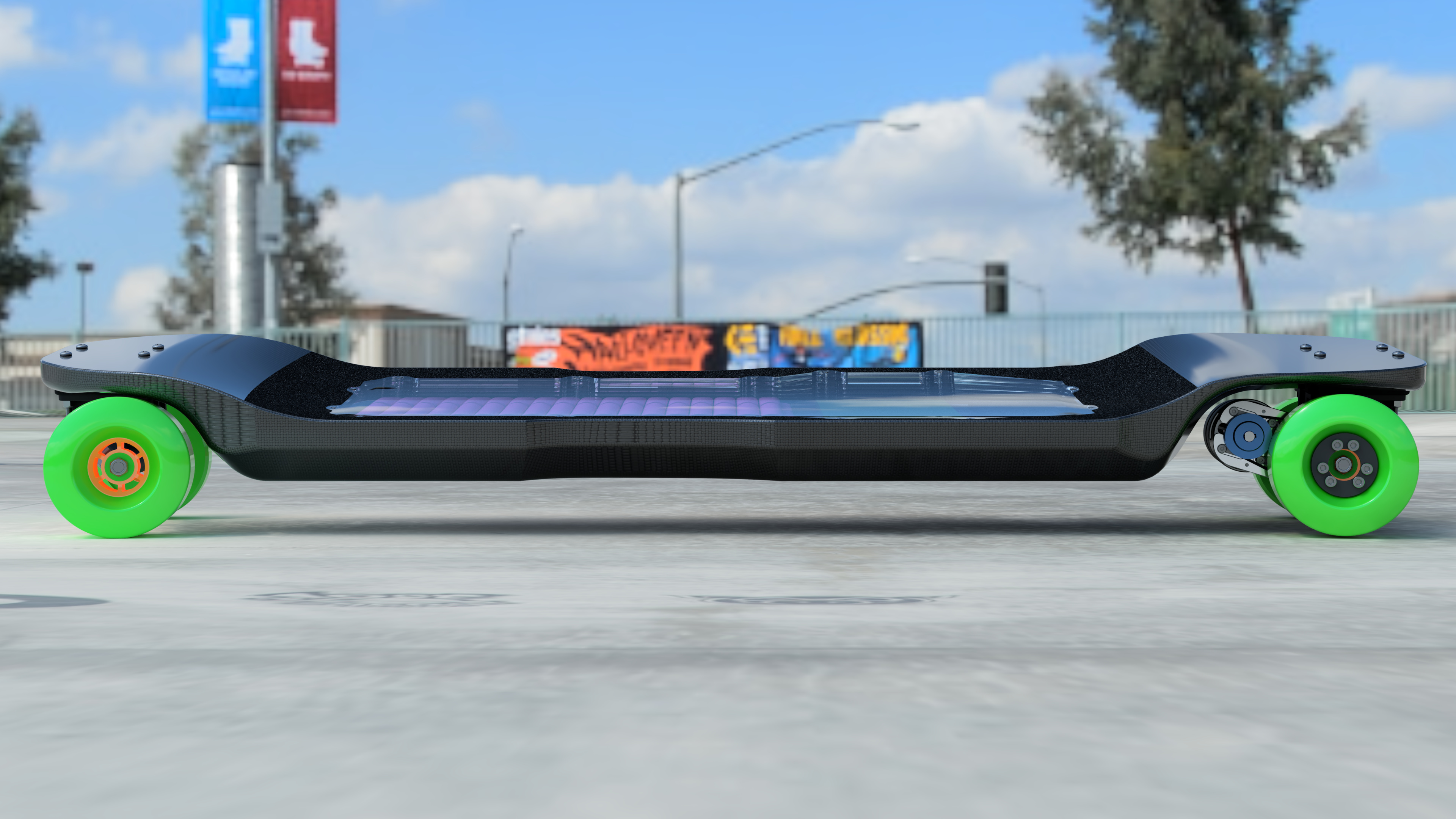
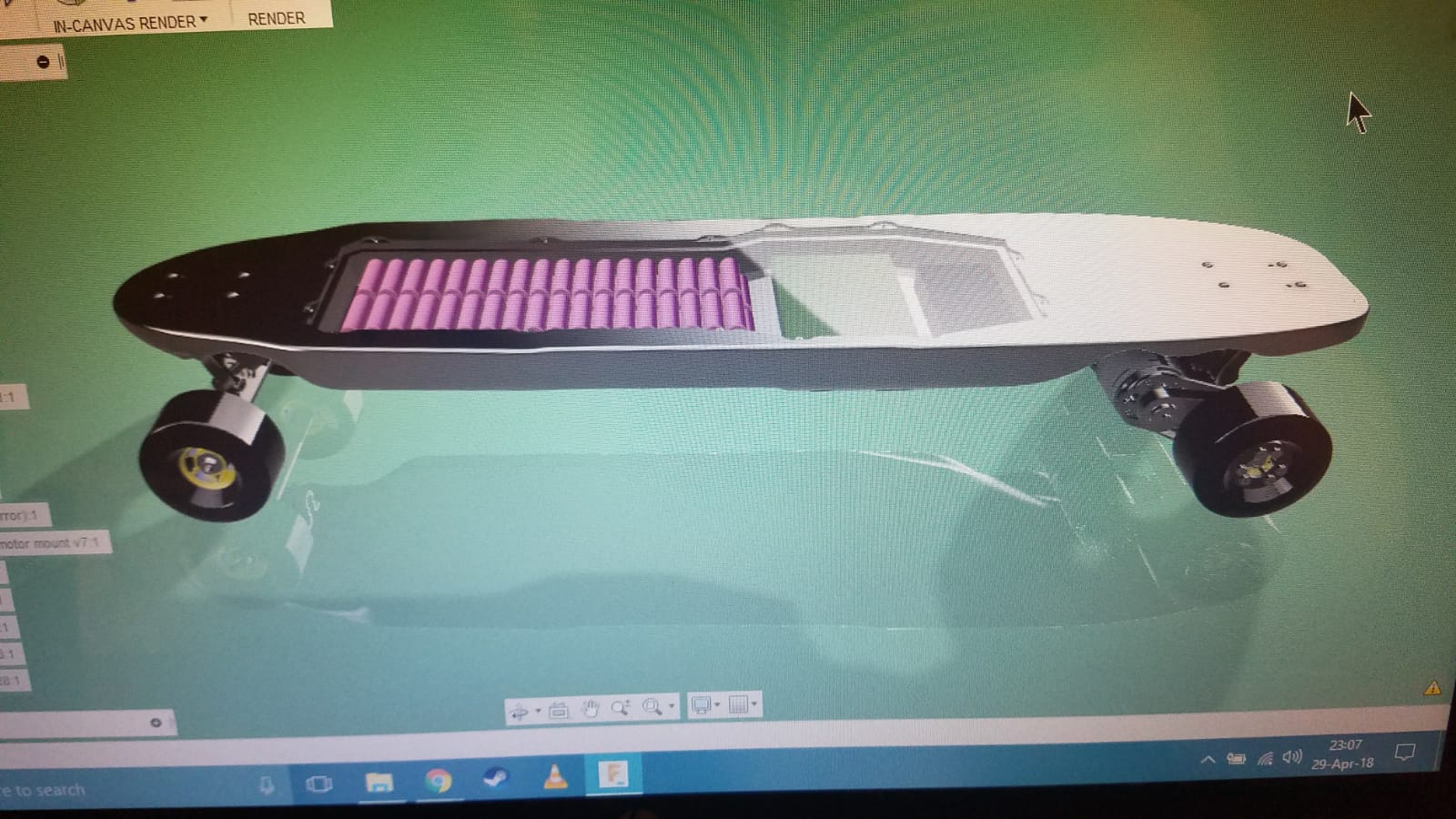
- Accomodate 12S6P in a stacked configuration like ....*.
- Designed to fit dual focboxes
- Designed to fit 12S Bestech BMS (largest part (width wise), damn…)
- Additional space incorporated for thin foam padding, wiring, recievers, BT, etc. Batteries are top to bottom though, may add a couple mm before moving forward though
- Designed cutouts around 107mm (108 to be conservative) superflys. Cutouts go all the way both ways at a 20 degree truck lean though, so smaller or similar size wheels center set, side set wheels should also be compatible.
- Cutouts for 6374 motors, fully extended away from wheels on Torque Boards motor mounts
- Should use at least 1/4" riser pads for clearance, I plan on using soft risers for additional comfort.
- Drop deck obviously…
- Simple deep? tub concave that extends ~3/4 of the way up the contours that hold the trucks, with an edge to center to edge (center depth) of 7.5 - 8mm
- Designed around TB 218 truck geometry, but any standard 50 degree caliber should work too since wheel and motor cut outs assume caliber/TB truck height/dimensions and extend as far as cuts could be made inward and outwardly (so wheel separation distance shouldn’t be an issue. won’t be modeling other trucks to check compatibility with say randals or paris though.
- Shape partly inspired by the 2013 Landyachtz Wolfshark, also loosely resembling the Longboards USA Road Warrior.
To Do’s:
- Verify compatibility with up to 5 degree rear de-wedge
- Integrate cable channels from enclosure to rear truck (after determining best MFG technique)
- Model individual pieces for manufacturing (press, foam cutouts, etc, upon determining best MFG technique)
- Take feedback!
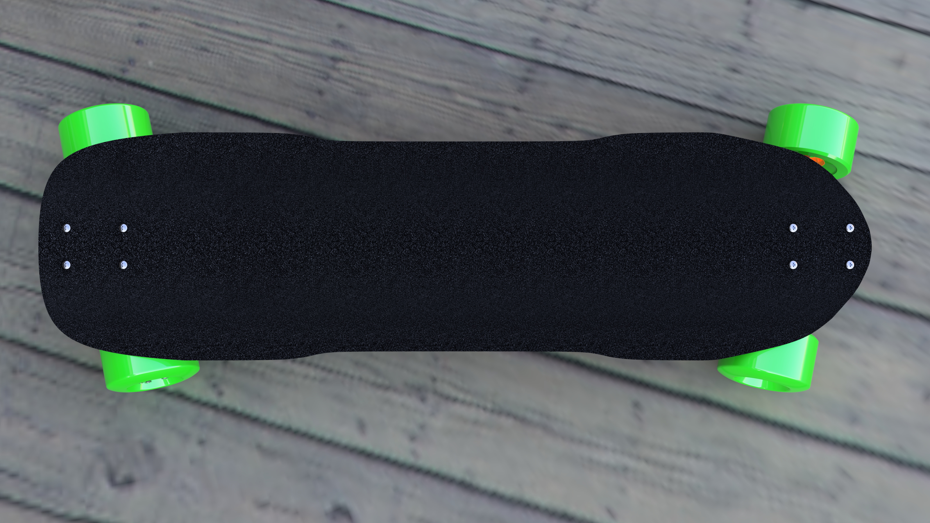
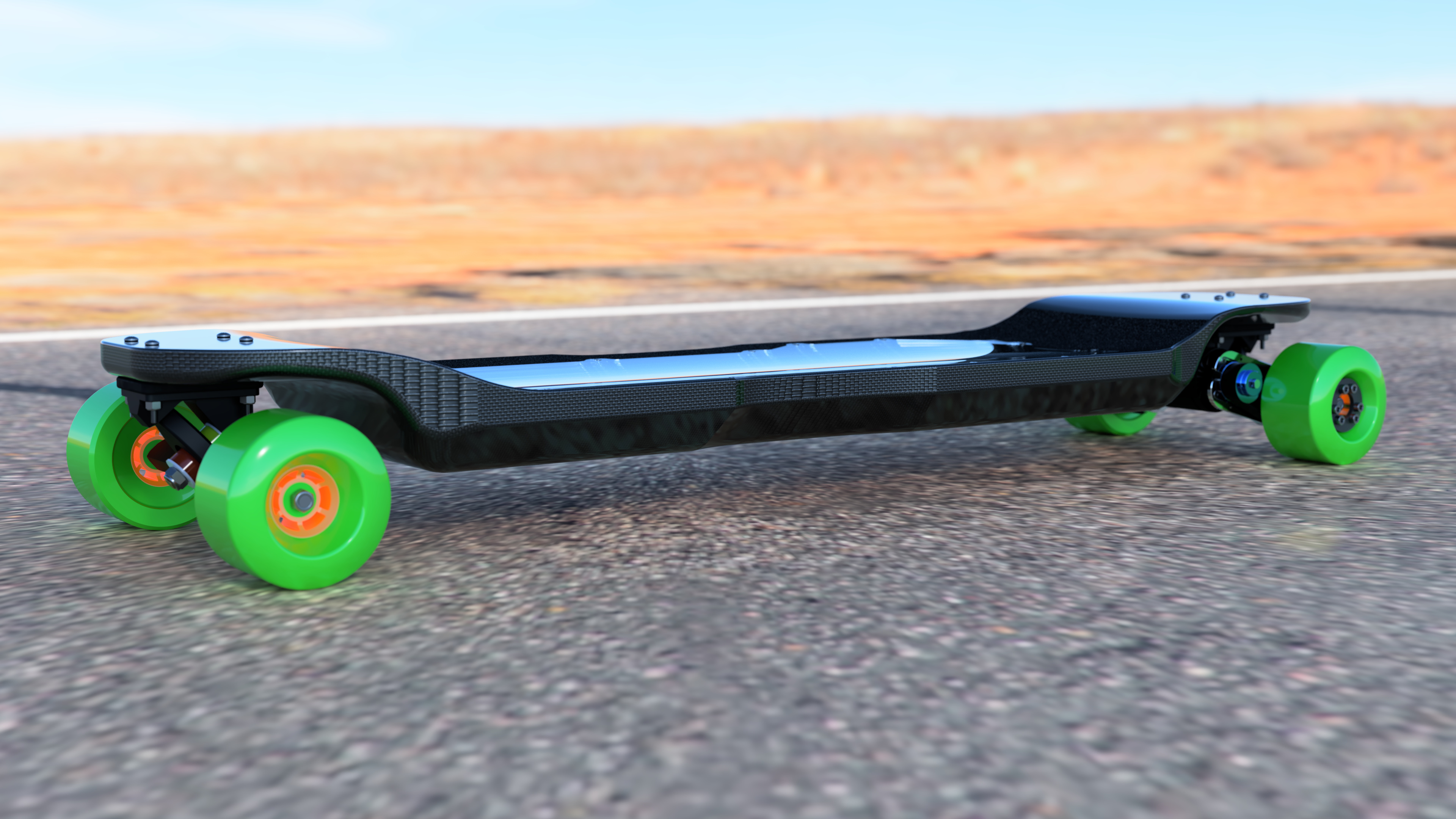
Finally… here are the rest of the renders. enclosure top clear to show insides. will be solid in the end. Enjoy!


Extra: shit shot of first iteration modeled after the loaded truncated tesseract

 A dream deck for many but not sure it’s possible to make it in reasonable price. Hope you can do it!
  I think you are over designing whole thing but it a nice way to go
  Projects like this one are fun