Just pleaseeee be very careful when working on the lipo battery connections.
Never CUT BOTH WIRES together, work one polarity at one time. Make sure to shrink wrap before cutting loose the other polarity.
Exactly what he said, wrap some tape around the lead you’re not working on so they don’t accidentally touch. I welded my scissors together by mistake my first time…
I saw that “slippy” made a 3d printed pull with a rope for the antispark. Is it supposed to be used in this way and should i make it accessible at every moment?
No 3d printed parts, and the small paracord pull tab was simply to make it easier to disconnect, and easier to spot if dropped (yellow w/ reflective in rope).
as for accessible at any moment - that’s not the intent, but w/ some ingenuity you can do this. This is a simple on/off (really an interrupt) with anti-spark built-in. cheap/simple. If you want an emergency stop you’ll need to make it reachable on your board - or connect it to yourself when riding. Problem with that is anytime you jump off you’ll disconnect power, or have a tripping hazard (depending how you set it up). I would rather stick to a simple on/off personally and not have a tripping hazard (falling sucks especially as tall as i am - a long way down!)
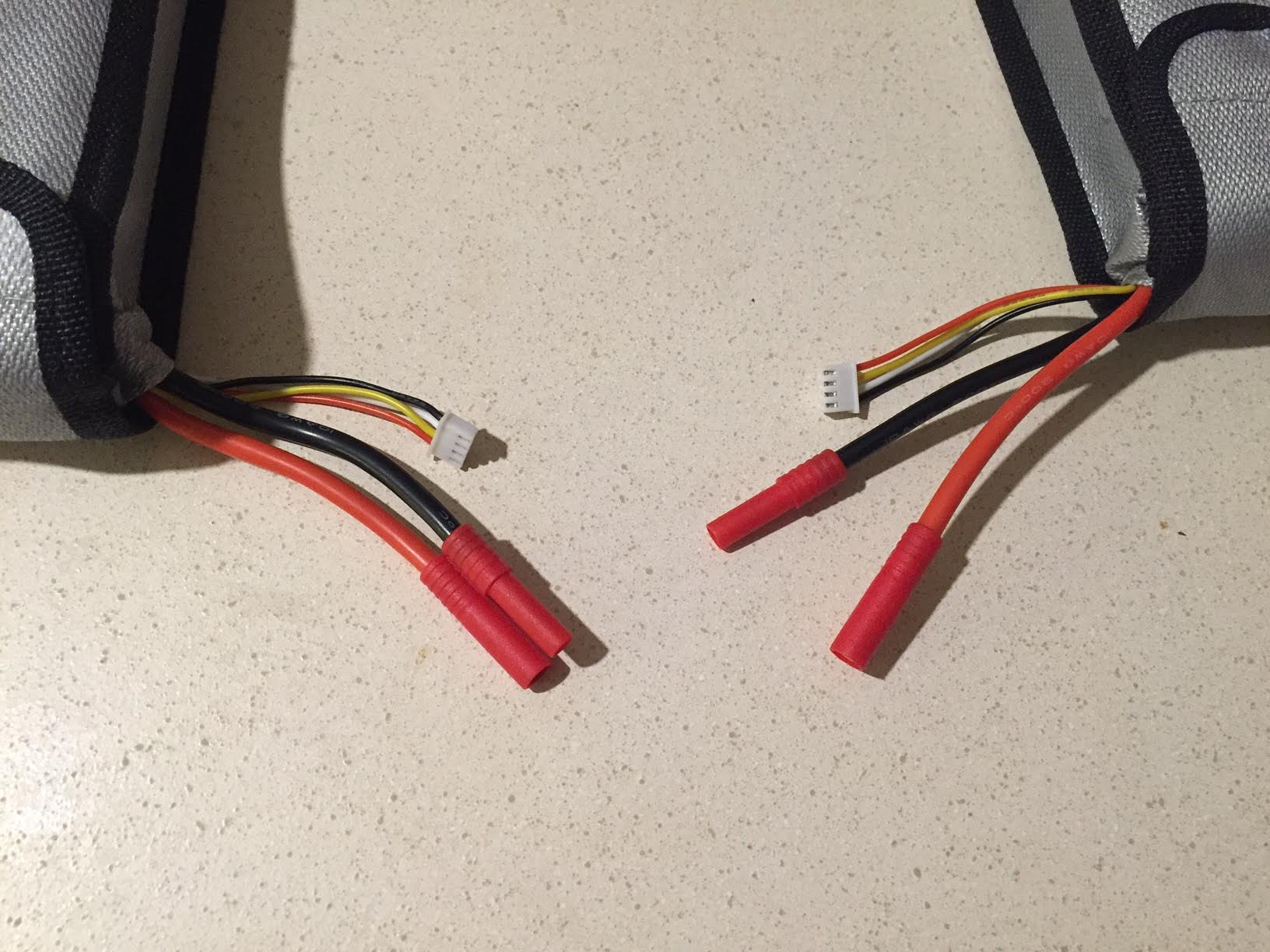
Those HXT connectors are perfect for wiring lipos in series. Take a razor blade and carefully cut the connector in half down the middle, to split the positive and negative battery leads. This basically splits the HXT connector into two 4mm bullet connectors with protective covers. Then you can directly plug A+ into B- to form the series connection. The leads of the battery pack are now A- and B+. You can make a harness with HXT 4mm bullets on one end and XT-90S on the other to plug directly into the VESC
@FLATLINEcustoms - that’s his bracket and super awesome IF YOU HAVE A DROP THROUGH DECK! Then there are quite a few other challenges around motor mounts and motor clearance, etc. This still wouldn’t really be an emergency interrupt without some sort of connection to your shoe/leg/etc. Still something i’d avoid as a tripping hazard and it’s not unusual for me to jump off - i wouldn’t want to lose power every time personally.
a loop key won’t let you charge - unless you do two. You are only inline w/ the + or -, so it won’t be a charging connector. Or you’ll need another port that connects to both + and - “behind” the loop key if you want to do this.
Looking at your batteries pictured - two 3s in series for 6s - you’ll want 3s to 6s balance plug adapters too if you want to have one connector for the balance plug, and the one for charging.
Here’s my rough quick sketch - hope it makes sense and you can read my quick scrawl:
I would have both the 6s balance and charging plug on the same side. It should be “behind” or on the battery side of the loop-key/disconnect (so your VESC isn’t powered when charging).
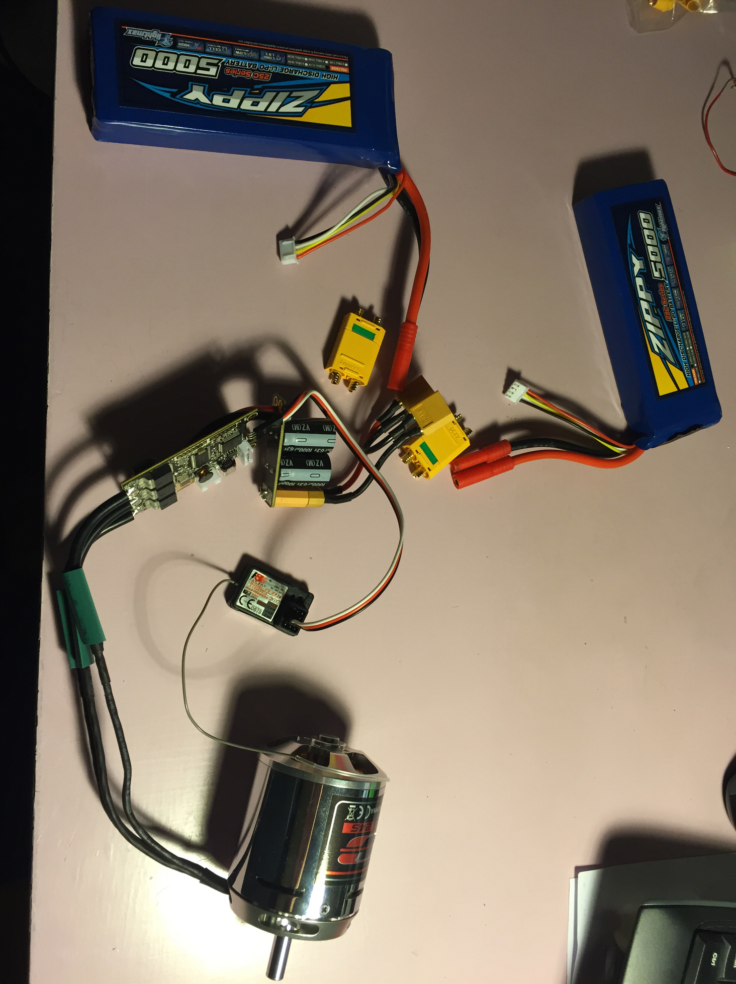
Well, that moment when you feel like you just conquered the world was right before I sat down and connected everything. So now I need your help again. Heres what happened and I dont know why…PICS
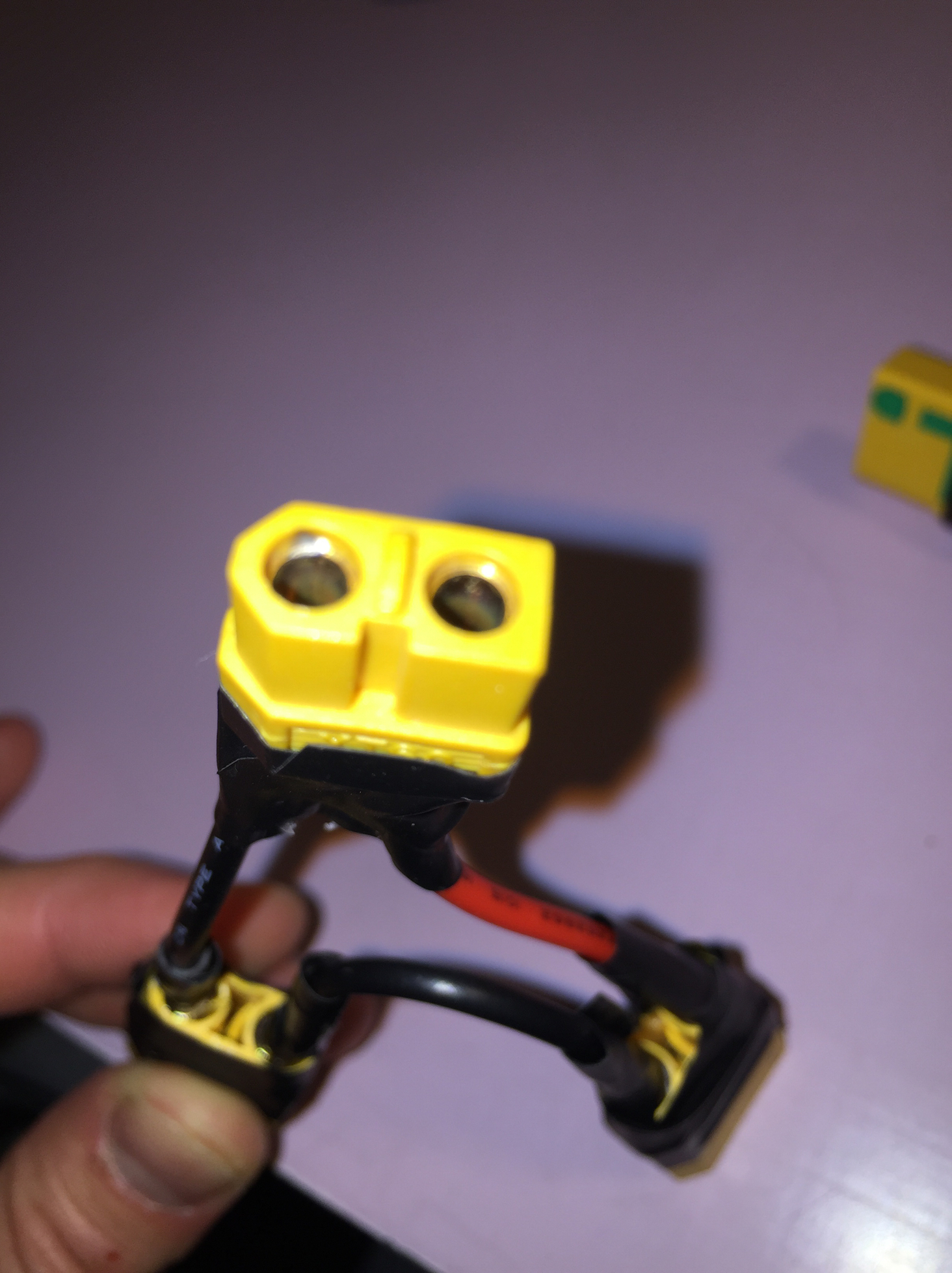
I got a spark on the xt60(pic2) when I was connecting the battery packs (connected together 6s/24v as on the pic1) to the VESC. Can you guys assume where the problem is?
So I manged to figure out how to put it together, but still have a bit of a problem. I did not finish the circuit completely, but have put the main parts to see how it acts.
In the end I will add pics that might explain my problem better.
Problems
“bad detection result received” when running a 2.18 fw
the motor doesent seem to give as much power as expected.
What does this step give me and do I need extra hardware to flash/upgrade like on youtube?
I did make the setup as instructed on youtube, and it has decent power, but I dont believe it will manage an uphill ride. Also it needs a push to get going and its relatively easily stopped by hand when upside down especially if the motor is cold (video). I did however try it only around the house since its freezing outside…
6S * 3,7V * 25A max battery = 555 Watts.
Just set the max battery amps to 60 or even 80 and the motor max to 80A.
That will make it much more powerful.
6S * 3,7V * 60A max battery = 1332Watts.
Also disapble the “Send status over CAN” for your single drive
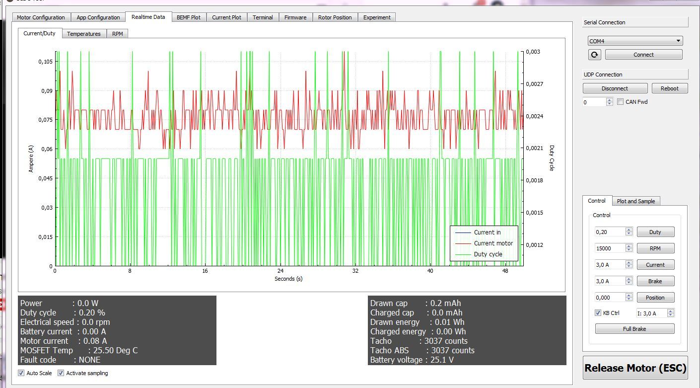
I put it both to 80 and tweaked the mount a bit so i got 15k rpm.
The board will not move by itself, especially with my weight on top (80kg). It seems to go ok with a slight push, but it has to do better than that from what i saw on the videos.
How relevant is this motor detection failure? Im on firmware 2.18, i dont know upgrading would resolve the problem and evenutally lead to better performance?
The board won’t move by itself because you have no sensors. So the VESC doesn’t know where the exact motor position is at a stand still. So you have to give it a little push.
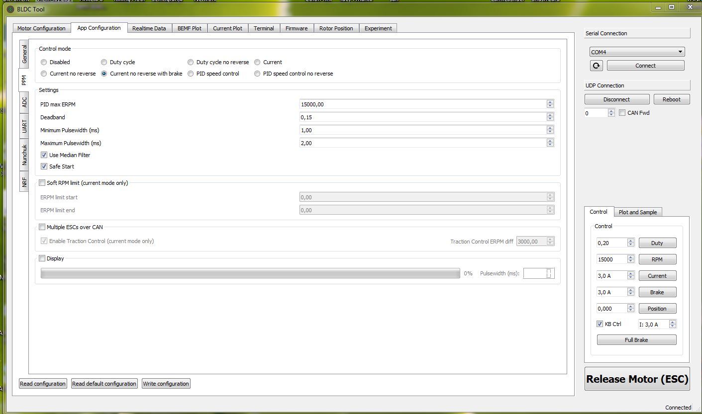
And please post a Screenshot from your ppm tab.