@mccloed said your pulleys are stretchy
oh god hope i’m the youngest one reading that, sounded super perverted lol
just use /s for sarcasm
1 Like
I still have some V1 mounts with 6mm S355 steel…try bending that stuff 
Is rusting/oxidising a big issue? Are they painted or powder-coated or bare or something else?
Powdercoated 
1 Like
I told you that in confidence!
1 Like
Oh!!! I’m sorry I thought the rash was in confidence…Or was it that Chaka’s motor mounts make you feel itchy?
1 Like
technically no, the space the device occupies stretches, taking the device with it. From the device’s perspective, nothing has stretched. But from the perspective of someone not affected by the undulating elasticity of space within gravity fields, the whole canvas gets pulled around, not just the subject.
therefore timing belts don’t stretch. lol
@chaka send me a set. If i can’t break them, i’ll endorse them! I need to get my lathe working anyway. And i have a set of cast ronins i don’t have any mounts for.
3 Likes
Hey guys been super busy last week. Sorry I haven’t been able to answer.
Yes science, Im an engineer. Real life experiment with many diff mount designs and realize a pattern then repeat and reproduced by peers.
Actually look at this thread from many years ago. http://endless-sphere.com/forums/viewtopic.php?f=35&t=72994#p1103124
Jason himself posted it and calculated through experimentation that any place on the mount with less than 6mm thick of aluminum will not survive.
Your mount looks ok. Mainly because your mounts thickness looks much more than 6mm thick(most mounts thickness). so that could help add strength for those extra holes. But i would remove them to be more confident. Side note i dont like the one sided clamp system. Make it double sided or no clap at all. Just set scres with a tight fit can work very well also.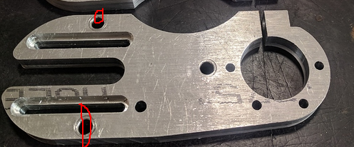
I cant say for certain since i didnt use them but @chaka mounts look sick. (@chaka Please send me them for testing/destruction) Even though they have many holes this is counteracted by much increased mount thickness. Or if you must have thinner mount to save space on your motor shaft then go with steel. like this one.
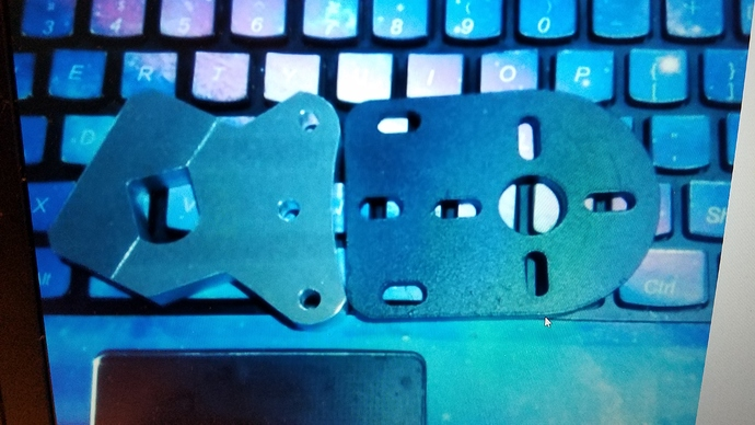 I copied the enertion mount and had it made in steel. Sorry in advance i dont have any more.
Also an example is the @Kaly mounts are designed very well.
I dont buy products that i dont think are designed well. Yes please send them to me for free and i will test them gladly.

I did not make this thread to say that i have broken yours. This thread is about education on bad design and how to improve it. So just from your pictures i see many places with material too thin. I just used your mount’s picture for an example.
Also i have broken my motors plate with screws also when that design was weaker than the mount was. again see this post from a while back.
Oh and @psychotiller ur nuts LMAO
3 Likes
@Mikeomania12. After reading this thread i need to redo my mount. Specifically increase the bolt radius for the trucks mount for a 40T pulley and reduce the idler slot size to thicken the mount at the edge.
Thoughts?

3 Likes
exactly you got the right idea
The problem with most motor mounts is not the motor plate, but the hangar clamp. Cast trucks have a lot of variability and require surfacing for a precise fit. Couple that with the fact that the axle on all cast trucks is very rarely straight, the axle diameter has too much slop, and the hangar facing is generally poor. Now you have a problem. A good mount needs to be both secure and perfectly square
CNC trucks and a two-piece steel clamp made my custom motor mount damn near bulletproof. I don’t even need locktite on the clamp screws
2 Likes
100%
The surf rodz are awesome on this point. 18.95mm face-to-face on all sides for the full length of the trucks. Makes my life so much easier - calibers drove me insane.
2 Likes
Please don’t be mad at me but this is not science. You just circle spots that you feel are too thin without any considerations for load, thickness, or material. Did you actually break all the mounts you posted in exactly those spots or did you do simulations?
Just take @MysticalDork mount where you circled two holes whose sole purpose is to attach a cover I assume. Those will see no forces at all - why would they need to be beefier?
Did you analyse clamping forces as well? Length of threads or bolt thickness should also have a big impact on how tight you can fit the clamp to the truck. Set screws might work but what’s the minimum size so that you don’t strip the head at the required force?
1 Like
Nah, those holes (and the one in the middle with the same size) are purely fixturing holes; For holding the aluminum stock in the CNC machine for profile milling. It was easier to just do that than to come up with some more elegant workholding solution.
You should market them as holes to attach a cover then 
1 Like
You bring up a great point, axle alignment. More importantly, wheel pulley alignment. Most pulley drives rely on either a bolt on adapter or an offset bearing race for alignment. In my opinion it is sloppy design but it works.
In our mount, the bearing for the wheel pulley is located along the center line of the belts path so all drive forces from the belt are directly transmitted into motion at the wheel. In contrast a pulley with offset bearings you introduce a bit of yaw when hammering the throttle and some power is lost. Sure I might be splitting hairs but, like a said before, you can feel the difference.
4 Likes
yup. its almost like an extremely subtle rubber banding at launch with the slightly offset bearing in the pulley. On mine the bearing sits just to the side of the belt line, not directly in it. Using a standard insert pulley i would need to remove way too much aluminum to be comfortable from my standard cast calibers to put that bearing in the belt line, but on precision trucks with larger diameter axles it wouldn’t be a problem.
your mounts are sick.