Hey guys!
I’m making a circuit with ATMEGA328P-AU as the “processor” with the Arduino bootloader.
It will be embedded with Vedders Anti Spark, NRF24L01(2.4ghz transciever), HM-10(4.0 bluetooth for IOS & Android), and UART for the VESC. I will create tutorials of making apps for iOS, programming the board etc.
I will make it open source when I’m done.
lol, I suck at asking, I meant is it reliable and how much voltage? Also I know now its reliable and it gives out 5V.
Im gonna run a chip and some lights. I am already doing it on my old e-board with no problem.
Its a circuit with inbuilt 2.4 ghz for remote, and 4.0 bluetooth for my phone.
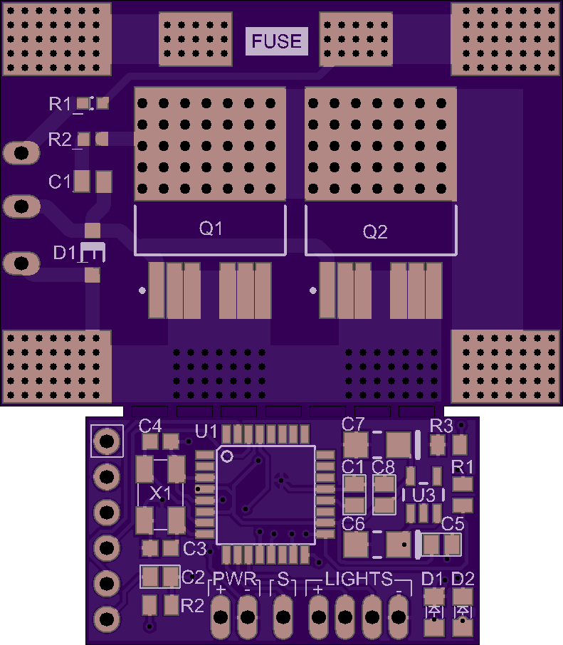
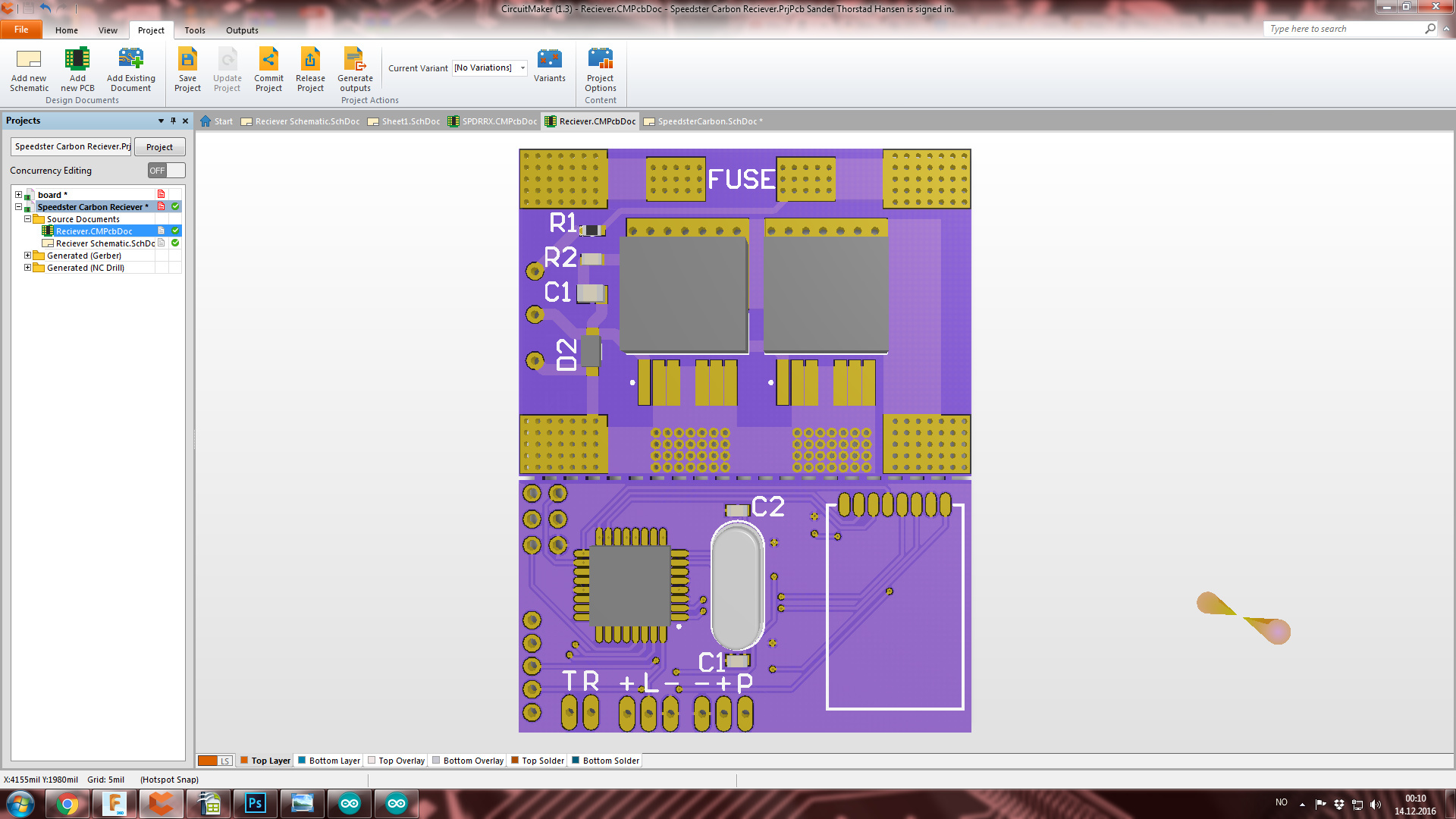
This is the circuit Im gonna use for my new eboard with inbuild vedder switch that I just made now:
I’m pretty sure all of the 5V pins are connected to the same circuit so it really wouldn’t matter.[quote=“Sander, post:6, topic:14608”]
Im gonna run a chip and some lights. I am already doing it on my old e-board with no problem.Its a circuit with inbuilt 2.4 ghz for remote, and 4.0 bluetooth for my phone.
[/quote]
Interesting. So two completely unrelated circuits on the same board? I assume the 5v has nothing to do with the vedder-ish switch?
Haha you are right. That switch tolerate 60V and 240Amp. But my circuit needs 5 volt to operate. And the bluetooth and 2.4ghz transciever needs 3.3v. So I have a voltage regulator that works from 4.5 → 7 volt that makes it down to 3.3v. The chip that I program on it works only from 1.8 → 5.5 Volts
Pretty sure the rule is that as long as you share you can do any imrpovements you want. So are you pretty much combining a hm10 and sparkswitch onto one board?
Im not sure if I connected the bluetooth right…
I connected the UartRx and UartTx to the pin D8 & D9(Arduino Pin).
And to the regulator 3.3v. And I connected all to grounds.
I would use PD6 as RX and PD7 as TX. Remember that HM10 TX goes to ATMEGA RX and HM10 RX goes to ATMEGA TX. Then use 3.3v VCC or 5v VCC depending on if the module has a voltage regulator or not and then GND to GND.