Where I could print these PCB’s? I know it is not the one I need (would need to create a new one)… but I was wondering where do people order them, for example in count of 10?
EU Sources for pcb making would be nice… as Thats where I reside
Anyways, what I mean is - I would like to get extra help to achieve what I have showed in the pictures…
I want to sort of create my own cell meter but my arduino knowledge is lacking…
All I know for now, is that I can use LM3915 can make everything easier to output to leds of bar graph.
Then, using arduino I need to divide voltage for all cell groups I need… as I remember there was something about dividing the voltage till it gets to 5v level, which the arduino can read.
So yeh, if anyone got that far, would be cool if you could confirm the steps which should be taken to create this… Im still not sure what else I will need to program and get before programming and so on.
Well, I think the problem lies in the customization.
The hobbyking module is nice, but for example, it does not allow more than 6cells in parallel, of course, it would be possible to connect next module… but would be nice to make the desired led count etc before hand.
I also checked some other options… so far the IDST module seems the best, but then again it doesnt have coulometer…
–
So yeh, probably need a few local people here who can help me out with this
You are right about the Voltage Divider, for a 6S 25,2V LiPo Pack you would need a ratio of about 1:5.1 to safely get below 5V.
Then you’d have to connect all cells via those resistors to the analog inputs of the arduino and read the individual voltages and also map them to their real values. By substracting the cell voltages you’ll get a delta, which is your individual cell voltage.
As for displaying the Values, wouldn’t an actual display be more efficient in this scenario? You could just hook it up and display the values of the cells or bars by programming the display.
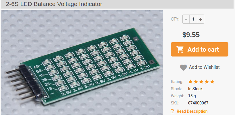
Instead, with a LED board like this you would need to do some sort of multiplexing to get it working just right, in addition to supplying power for all the LEDs using additional transistors (the smaller arduinos can only supply 200mA total).
So, my recommendation would be a simple OLED Display that is controlled via I2C. There are even colour OLEDs which could reproduce the bars exactly.
Yeh, thanks for summary. I have 16x 2 display lyinh around but i somehow never got to programming it.
I think i will just think about this.in the time to come, the idea.about these little dots / bars just seemed to be good looking and sort of retro.
I guess.i just need.to rig up arduino and get to the point where.i get the needed.values / voltage levels, after that i can choose.which way i want to go to display it.
Somehow the led graph idea seemed.simple, if i could use another chip which helps.with controlling the leds
–
Part of reason for this would be to have one more indicator to tell voltage level and also keep an eye on individual cells.
It’s not recommended to use voltage divider for measuring voltage of battery cell in multicell application. U will have really poor resolution because one cell is 3.7 and another is 35V. At the moment I am working myself on small balancer which needs to measure each cell voltage.
I started looking into this in more detail on a random night, he’s right at a certain voltage the resistors would dissipate too much power. you’d need 1w+ resistors which are huge. and it becomes wasteful.
I started looking into optto isolators, I think its the way to go but at that point its basically the start of a full bms. which is not a bad thing, but it will take more time and work…