I’m using two VESC to control a two wheel drive system made with sensored hoverboard wheels and a 36V Lipo battery.
I would like to get some advice about how to wire/connect my arduino to my two VESCs. I basically want to send velocity commands. Ideally i would use an arduino micro or uno (smaller size) or another equivalent. However, I may use a Mega and leverage its several serial ports.
should I communicate with each VESC independantly? or should i have one “master” VESC connected to arduino and the other VESC connected to the “master” through CAN bus?
should I use UART communication? (https://github.com/SolidGeek/VescUart would be nice to send exact velocity commands instead of sending a PWM and hope for the best)
I tried the later. but unfortunately both servo.writeMillisec() and analogWrite() do produce a PWM that I can see on my oscilloscope, but seem to have no effect on VESC whatsoever. In vesc_tool, in app > PPM settings > mapping, it looks like the VESC does not see any signal at all. However it works just fine with my hobby RC receiver and remote controller though. I just connected arduino GND to the black wire of the VESC PWM cable and used the signal white cable to inject my PWM. To no avail.
What should I do to see that PWM in vesc_tool?
What connection/architecture would make more sense to control a dual VESC setup from arduino?
first of all, i managed to find out why i didn’t see my arduino pwm/ppm in vesc_tool => there is a “RP app” button that somehow ended up disabled. now that it’s clicked, I can see the input… making some progress
Yes to one ESC only and CAN. You don’t want ground loops! Also be careful to not create a ground loop between the Arduino and the master ESC. Powering up the arduino from the battery via DCDC converter and having a connection to the ESC is a guarantee to create a loop. The voltage regulators would fight against each other and one of the will likely fry. UART would be a way to go.
Best thing to do is to use a can bus between the controllers and send ppm to the master.
(can is a bus protocol that allows the vesc to communicate to eatchother)
PPM is a communication protocol and changes the length period on eatch rising edge. To use PPM in arduino include the servoes libary. It uses the same protocol.
You will have a potential between two devices, hooked up to different voltage regulators.
Y-PPM causes a ground loop because both ESCs are hooked up to the same receiver (powered by one of the ESCs).
Both ESCs feature voltage regulators, which do not have a 100% perfect identical voltage output (lets say say 3.25 and 3.35V). So there is a potential in between the two outputs.
Both ESCs share a common ground via the battery already.
If you now interconnect the voltage regulators from both ESCs via a GND link you create a ground loop and the regulators will start to fight against each other. One will to try to regulate against the other.
This usually ends tragic for one of them.
To simplify things: If two devices share a common ground you should not have an additional GND connection in between components of the the two devices.
The ESCs should therefore be interconnected via CAN only (CAN H and CAN L wire ONLY).
You can easily create a similar ground loop using an external controller like an Arduino.
If Arduino and ESC components are powered up by separate DCDC voltage regulators things will potentially end tragic for one device if you create aground loop.
i understand I need to connect VESC master to VESC slave using CAN like this =>
(i still need to make the right connecting cable… in progress…)
However, I am still confused about how to send commands to the master VESC without creating ground loops. and for starters how to power the arduino micro using the master VESC.
I was thinking of use the red/black wires from the PPM cable of master VESC => this is ok?
assuming yes, now if i connect the arduino micro to a USB PC => then i create a ground loop, due to power and ground from USB/PC ? or no?
assuming powering without ground loop has been achieved, for sending the signal to the master VESC, i’m still confused
build the PPM signal from arduino micro (both signals for the two VESC on a single data wire) => then connect this data wire to the white control wire of master VESC. In that case, I still need to figure out how to merge the two signals on a single wire from arduino (no clue)
use the TX/RX of arduino micro as demonstrated here => https://github.com/SolidGeek/VescUart/blob/master/examples/getVescValues/getVescValues.ino
However, in this library, I do observe a void setRPM(float rpm); that should be just fine. But I struggle to understand how you specify which motor on the CAN bus should use that RPM. I also see void setNunchuckValues(void); Maybe to control both motors I need to configure both VESC to use nunchuck app and send nunchuck values from arduino to VESC master? I feel confused here
On the other side, the RollingGecko VescUart seems to support COMM_FORWARD_CAN but looks a bit harder to integrate, seems discontinued and may not work on 3.4 fw?
I guess i’ll have to try them both and see what happens
I did not manage to compile the RollingGecko sample (using arduino 1.8.6 on a win7 computer)
I manage to compile and upload the SolidGeek sample on an arduino micro using the same PC.
However, it keeps claiming Failed to get data!
I tried to make several UART cables, I checked the 5V/GND with oscilloscope. I tried reverting TX/RX. I tried with two chinese VESC copies and two FOCbox units. Always checking that the VESC app config had UART enabled. I had a friend checking connection and everything => to no avail. nothing worked. I keep getting this Failed to get data! at runtime as is no UART cable was plugged at all.
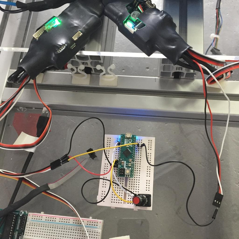
Out of despair, I moved to using a potientiometer on arduino (5V/GND from one VESC pwm cable) and no USB cable on the arduino. I finally managed to get one VESC to spin with the servo.writeMicroseconds API
Then, I just injected the same pin in the second VESC (without plugin the GND pin…). Both wheels do spin at the same time and at the same speed. Indeed the vehicle does go forward and reverse as expected.
There is a updated uart data lib: https://github.com/RollingGecko/VescUartControl/tree/VESC6
This i for the vesc6 software, im not sure if theres a difference from vesc4.12.
To use uart, you need to connect arduino to RX and TX of the master vesc.
You can use i2c instead of ppm, but im not sure if you can send speed commands over uart.
I would suggest running them in master slave config