I have some SolidWorks models ready to go for that. It’s a one piece model which I assume makes clamping it down a little trick so I was also going to a just it for a two piece version where the pulley portion is exchangeable with different sizes. Plus you can probably hold each piece more comfortably on your CNC.
Though I have never worked with one personally so I’m not familiar with reasonable limits and processes for setting up and milling with a CNC
I have totally remeasured some ABECs I got and have 3D mostly there in Fusion360 (killer free CAD/CAM)
I settled on a 3 part design. The hub washer, the cone and the gear. I am thinking it would be a better strategy to be able to change gears on the cones and be more economical because it would waste much less gear Blank. I am avoiding cutting the gears at this point because you need a special milling cutter to cut the splines as I am making wide gears too wide for a skinny endmill to cut the contours of the gear.
Sorry if thats hard to follow but thats the logic behind my approach. If anyone sees an opertunity, feel free to reach out.
I believe I never did get around to posting the cad models online, you had asked for it right? like as a reference. I’m 5 days away from finishing exams and once I’m free of school I’m gonna spend some tine and finish off the design I started and upload everything. I’d be interested in learning more about the CNC/Milling process as well if you wouldnt mind walking us (me) through how you’re doing each part and so on. I realized I have access to the machine shop at the university and I may end up trying to make a set since I’d only have to cover the material costs but I really dont know enough about how to approach this to not hurt myself or their equipment.
All,
So the puppy was being very needy so I didnt get much time cadding.
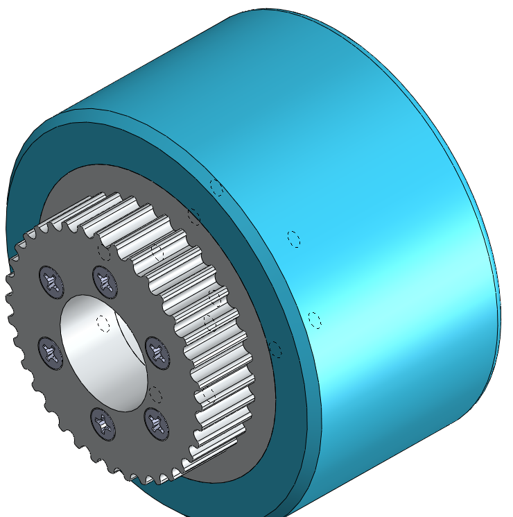
I came to the same conclusion as @mainstreet, that the best design to fit different gear sizes is to have a three piece design, Outer Wheel Mount, Inner Wheel Mount and the gear itself.
The gear stock can be cut to whatever length belt you want and the number of teeth can range between 30T-42T, I can go even smaller if I use smaller screws, I just have to verify the loads and make sure we won’t shear them.
There are no mods needed for the trucks as I’ve made the hole large enough to fit the Caliber 2 Trucks.
I will be uploading pictures later as I had to start work 4 minutes ago.
I will be ordering enough stock to make (12) 36T-15mm sets.
The cost is looking to be like $22 for the set + whatever shipping my way and shipping your way.
If there is enough interest in other sizes I will order gear stock for other sizes.
Stock will be ordered tomorrow so that I can machine stuff over the weekend.
Who is definitely in, for how many, and what size?
So far I’m only doing 36T but the stock for other sizes is $100, divided by the number of people that want that specific size.
Please reply with
Commitment, quantity, size, length.
I still need to simplify the fillets to make it faster to machine but it won’t change much if at all…
To change the teeth number, remove the inner 6 screws and replace with whatever size under 42T…
I’m in. Looks awesome. I’m In. I’m using 38T 15mm wide (measures 16.5mm) but I can make my own pulley if needed as I have 38T stock. I am really interested in the wheel mating component.
Committed, 2, 38T, 15mm (no pulley for me if the numbers aren’t there. just the core)
Update:
I am thinking that the best way to reduce weight is by having the wheel attachments 3D printed.
The PLA filament for my workplace printer runs about $30 a roll.
What I’m thinking is having clearance holes through both inner and outer wheel attachments and tapped threads in the gears themselves. All of the loads then go directly through the bolts so there wouldn’t be much stresses on the wheel attachment.
The only downside is that the gear gets slightly more complicated since now it also needs to get tapped. Not an issue for me but it wont be as straight forward as just drill 6 x size holes…
Just came to mind that we could also do countersunk hole on the gear and nuts on the outside of the wheel.
What are your thoughts?
We either need to decide on a single Gear stock or wait on more people to order because as of right now we have:
2 38T
2 40+T
2 36T.
and I myself am good with any between 36T and 40T as my gear ratio is between 2.25-2.5
I am fine with anything.
5 mm (HTD) Aluminum Alloy 38T $117.45
5 mm (HTD) Aluminum Alloy 36T $110.22
5 mm (HTD) Aluminum Alloy 40T $124.95
Cost will be divided per pulley, in this case almost an even 4way split.
These are just my thoughts on the topic but so far it’s looking good.
From a perspective of effective mass, the additional weight of the aluminum spokes is nothing compared to that of the pulley with will be further out and have the same angular velocity but faster linear velocity. The strength benefits of doing the whole piece in aluminum I think outweigh that of reducing the mass marginally especially where it’s affects are not critical. By whole I don’t necessarily mean one piece, the entirely aluminum based.
You don’t necessarily need to match the inside profile of the back of the wheel either. The spokes do the alignment, the rest is just there to support the pulley. You could get away with removing material from the fillets and do a step instead of a slope. Much easier to machine and quicker.
That being said if you want to go with 3d printing then I would agree clearance holes and threading right into the pulleys is best. You’ll have to overshoot the tolerance with the 3D printed portion since 3D prints are going to be a little more sloppy than your CNC Iin terms of tolerance
I am same as @Bender count me in for 2 x 40+T, really prefer 44T lol. Am up for 12mm or 15mm, don’t seem to be able to source 12mm belts as easily avail as 15mm imo