Balance Wires for 10S3P

Hi

I have bought a 10S 80Amp BMS

I have no idea where to solder the balance wires, or where to learn

I am creating a diagram of all components so I can double check with the forum before I mess anything up, but I have just started so bear with me :slight_smile:

This is my first build and sorry for stupid questions. There are other threads with similar questions but I want to be cautious

Diagram

I found this, but the image doesn’t clearly show where the wires go, or they do go where it says?

image

https://esk8content.nyc3.digitaloceanspaces.com/uploads/db2454/original/3X/7/f/7fc83e1a704c86b660b9f0947a444e3b898e8c85.jpg

1 Like

I mean on the battery

The connect to the nickel strips welded to the cells. Soldered onto the nickel in-between cells

But which cells? Theres 10 wires

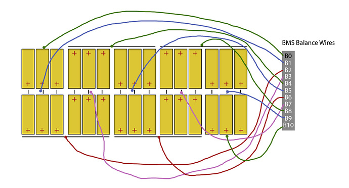
B- is the negative end of the battery B1 should be about 3.7V higher than B- B2 should be about 3.7V higher than B1 B3 should be about 3.7V higher than B2 B4 should be about 3.7V higher than B3 B5 should be about 3.7V higher than B4 B6 should be about 3.7V higher than B5 B7 should be about 3.7V higher than B6 B8 should be about 3.7V higher than B7 B9 should be about 3.7V higher than B8 B10 should be about 3.7V higher than B9 B+ should be about 0.0V higher than B10

2 Likes

So for the sake of the diagram, do you know if the one I showed is right

Yep it’s correct

No, the first image is not correct. The red things that say 12AWG should be gone

This is correct https://esk8content.nyc3.digitaloceanspaces.com/uploads/db2454/original/3X/a/c/ac78dd4bdfaba6e746c613d4fdf28848a538771b.jpg

1 Like

I’ve seen people connect 12awg wires

I thought I’d do the same?

@darkkevind

So B2,B4,B6 go in between the cells and on the nickel?

What do you mean by in between and on the nickel 
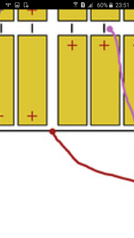
If you mean does the wire get squeezed in between, yes if you don’t add a tab of nickel that’ll fold over the top to connect the balance, that would be preferred

Yes to that too, those are 2 diff P groups

And it’s a good idea to bridge the 2 parrell groups with 12 AWG

The first image above is not correct, I fixed it here:

2 Likes

If up to 50-60A that’s fine, if more, then 10AWG

@moon look at the diagram @b264 posted, make sure it’s like that, your original diagram was incorrect

1 Like

You would be bridging the SERIES joins with what should be 10awg wire… not 12awg.

Those wires are also nothing to do with the balance leads… they’re the main series connections of the battery pack joining the paralleled cells together in series.

2 Likes

I know that they were unrelated to balance leads, but I just drew that on the diagram.