I’ve done some more digging, thinking and tracing the PCBs
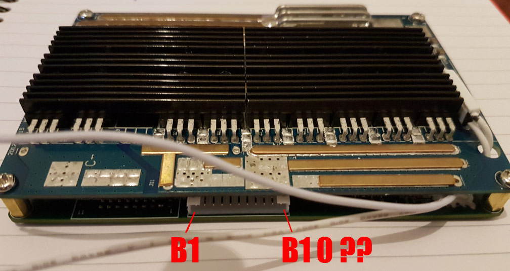
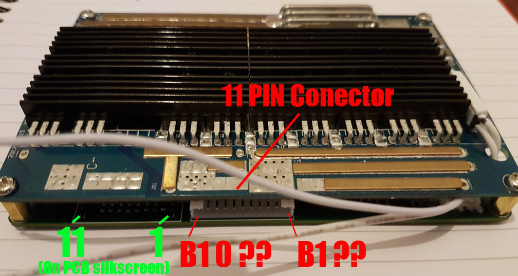
There is a place for another balance connector to the left of the balance connector, this has a silkscreen label of 11 - 1. It is impossible to check the silkscreen of the balance connector (without desoldering) in use as it is under the connector
Stuff in Green is confirmed by the PCB silkscreen
Stuff in Red is up for debate
The balance connector is 11 PIN just to really fuck with my head, as all of the other Bestech 10S BMS I have seen use 10 PIN connectors…
That looks correct, first pin would be B0 I assume
Also possible it has P+ and P-
I would grab a drained low discharge cell if you have one and hook it up to b-, b0,1 and test the pads, though I’m not sure it would function properly without the full series…so maybe a test 10s1p pack
Put a 1a fuse on it or something if you have
I think I am going to have to wait for the wiring diagram.
I am not one to shy away from a good session of hunt the trace, but when it comes to high amp packs there is no room for error and I am already short of BMSes to fill backs orders that have come in so I really don’t want to bork the BMS
it should be easy to check if the first and last balance pins are connected to positive and negative using continuity check on a multi-meter. if so the other 9 pins will be the intermediate balance points and it will also tell you which direction they go in.
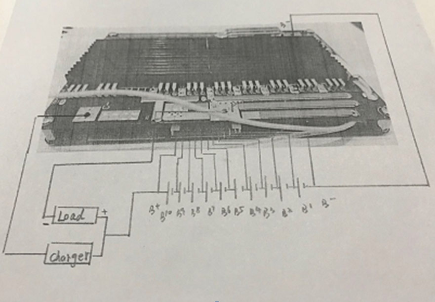
Steps for how to connect the PCM with cells in order.
Connect Pack’s negative with B-;
Connect cell 1 with B1;
Connect cell 2 with B2;
…
11.Connect cell 10 with B10;
Then measure the cell’s voltage in order to see if the voltage is progressive increase.If yes,you can plug the connector to the PCM in order. Also if the connector and wires is not matched,please don’t plug,or the PCM will be damaged.
12.Connect Pack’s positive with B10;
13.Connect Load’s negative with P-; Connect Charger’s negative with C-;
14.Connect Load’s positive with B10; Connect Charger’s positivewith B10;