Hi, I was looking to buy some mosfets and make my own Power Switch. But I read that some Bms have power switch and I questioned my self, can I put a power switch in my Bms without all that Mosfets and things that have in a Anti-Spark Power Switch? Look at the bms 

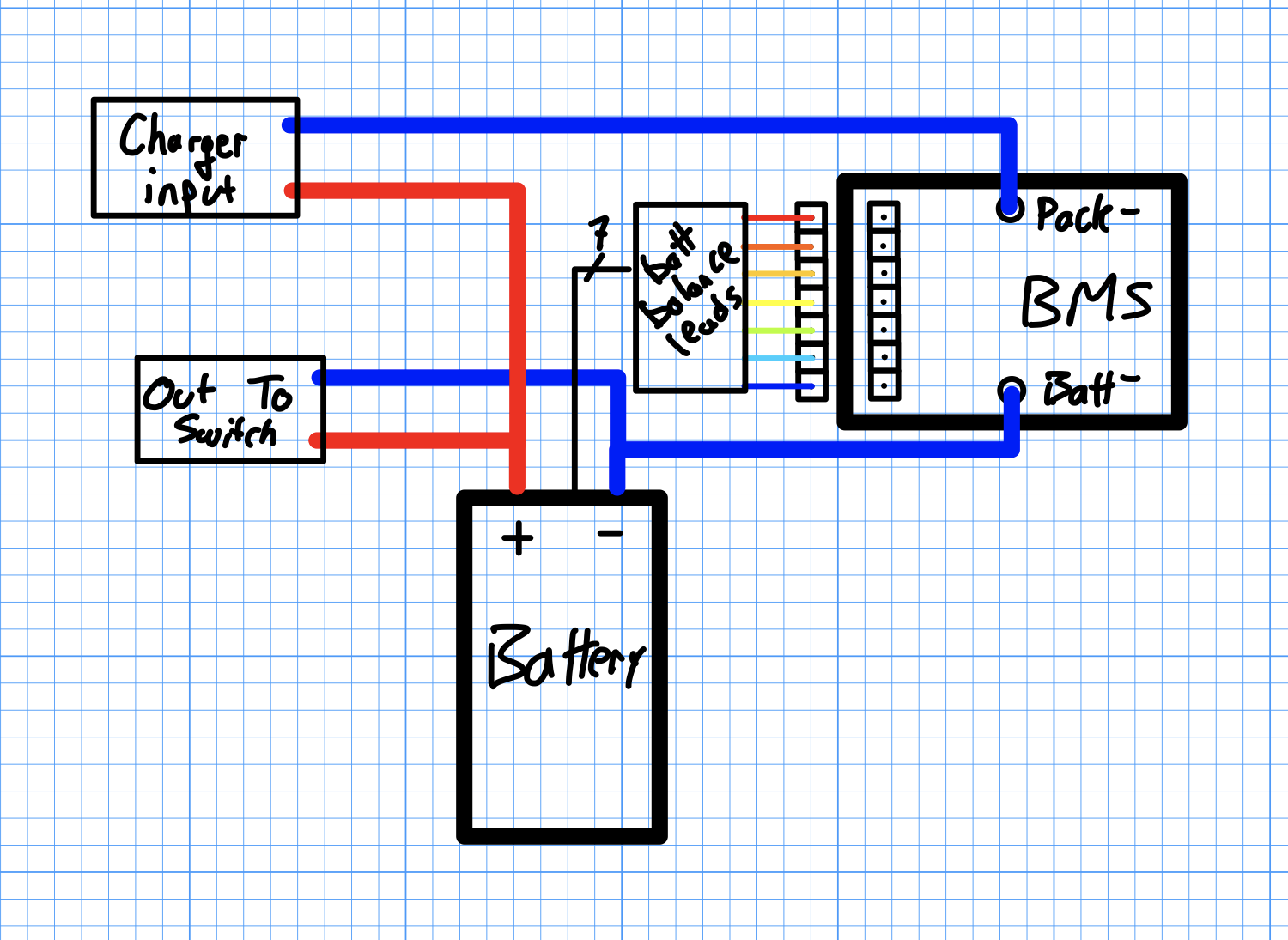
I don’t think so Besides, that is only 20a BMS. You are going to need to bypass it on discharge and use it only for charging. And by the way, the wiring diagram. The numbers on the balance wires are backwards. The cells count from the negative side of the battery 1-2-3-4-5 with the red balance wire being cell 6
Yeah, but if I put a Power Switch without all that anti spark mosfets, it would work?
Right here is the squematic of the Bms
i hope you’re joking, that schematic shows a switch that doesn’t do anything except short the battery
Thats how you turn it off! Permanently
1 Like
Sorry, a guy on this forum said to Me do this way, what is wrong? Or are u talking about the Bms Squematic?
Why? It will blow my Battery?
Consider: if the circuit is closed at your switch, what is the most direct path from the + to - terminal of the battery.
1 Like
I Understand it, but my diagram is correct? The one that is Colored okay?
It isn’t correct. You’re connecting the + and - poles together
Noooo, positive will pass under the Negative one
I’m talking about the switch. You are still connecting a + and - together
I’m sorry, where I’m doing it, there is no switch in my diagram
threads like this make me giggle.
these are the ones that directly precede the “I connected my battery and there was a big spark and now nothing works threads”
and then the “don’t buy this switch it killed my battery” threads
seriously… you diagram is wrong. the “out to switch” causes a direct short of the battery.
smoke then fire.
2 Likes
i think you don need a switch for BMS, but for your ESC… just a key loop will solve…
You have a few options here instead of making it work against all odds…
- Buy an antispark switch
- Buy a smart BMS or BMS with a switch circuit built in
- Make a simple XT 90 loop key
@IsTalo, everyone is wrong, the schematic is correct.
They are confussing the “Out-To-Switch” with an “on/off switch”, when it’s just an switch with positive and negative poles which would to connect to the ESC and then to the VESC.
Here is my diagram if you want to connect the BMS for charging only (recommended)
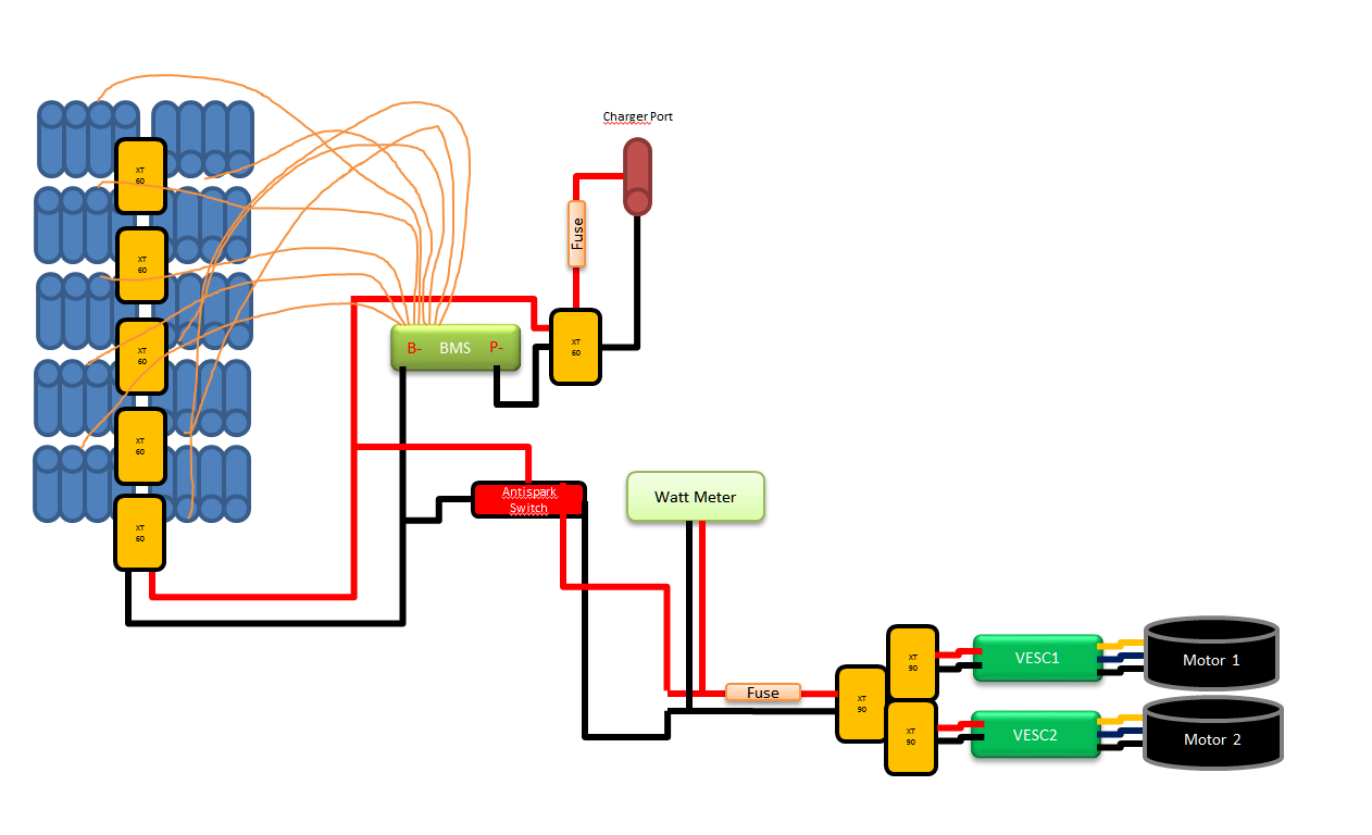
2 Likes
tat is the greats diagram. I think @IsTalo should draw out the whole system. we only know understand “Out of Switch” meaning…haha.
BTW @Eboosted, i have a problem on integrate BMS to my setup, are you connect balance lead to BMS first or main power wire first?
O didn’t get your question very well.
In order to fit a BMS you must connect BMS B- to battery negative, BMS P- to charger negative pole and balance leads to all possitive pole en each pack
