i have some 22awg bare bus wire but have concerns that it won’t be thick enough to carry the amp output of each cell.
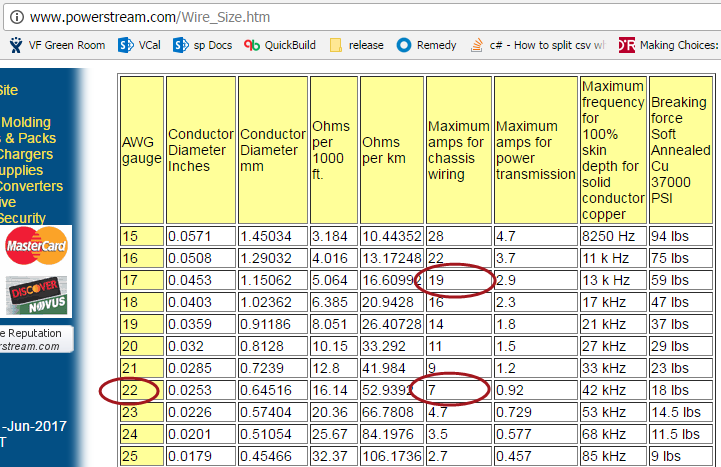
looking up wire gauge current ratings, 22awg seems to be rated at 7amps. i know current capacity varies based on temperature but this should be a decent indicator.
i think the question answers itself, but it seems i should use 16awg to be able to carry the 20amp continous discharge these cells are capable of producing, right? is there some nuance i’m missing? also, would it be possible to coil this 22awg wire to double its carrying capacity?
Fuse size is a different spec than power transmission. FYI the smallest pack I have ever built is 10s6p. The cells will be under a larger load in a 10s3p so 22 awg may or may not be up to the task. The goal is to have a fuse that will still blow if a cell internally shorts. This becomes more difficult to spec in a small pack since you are relying on the remaining cells in parallel to produce enough current to blow the fuse on the offending cell.
I’m just going to double up the 22awg wire, twist it together, and try to run 20amp then a lot more than that as a test. I’m hoping they’ll hold up at 20amp, and blow at 30+amp. We’ll see.
i’m just confused because these wire gauge specifications are saying 22awg is good for 7amp. i’m confused.
@Titoxd10001 also told me 22awg is good on his 10s4p pack. assuming motor max is 60amp, a 4p pack would mean 15amp draw for each cell. my 12s3p pack will be 20amp draw.
yea, i think i’m going to twist 22awg wire together and test it.
22 awg nickle plated copper wire will blow at approximately 40 amps depending on the length of the fuse wire. If you double it up they probably wont blow.
I’m uing 22awg wire in my 11s4p pack and have pulled about 80 battery amps peak. Holding up good so far. Soldering was a pain over 200 joints I think lol
@chaka are you still using cell level fusing? And are you using cell holders still or a new method?
Cool. Do you have more info on how everything is secured. Is silicon holding the cells together? Fish paper has adhesive for the buss bar I’m guessing? And how do you secure battery packs to the board.
Some of those extra solder poitns you see on the buss bars are because the fusing broken (probably from vibration), so instead of lifting the buss bar to resolder underneath, I just soldered on top.
Thanks, your images helped for my first battery build. What i wanted to understand is how chaka was keeping everything together because he no longer uses 3d printed cell holders
The fuse wire broke? It seems quite flexible. Do you have your cells and the bus bars glued down? Wondering if I should be worried about my pack now
the bars are hot glued to the cell holders, but the pack is loosely sitting in the case. It could be higher internal resistance causing the wire to blow too, i did put two wires for one of the cells since it kept breaking.
I wouldn’t have thought vibration could break a wire. Your cells are glued to the cell holders? if not they can possibly rotate causing stress on fuse wire. I use 22 awg and working so far. I do have double side foam tape, maybe that adds a little extra dampening. The wires I can visually inspect look good and voltages looks good, but I’ll try to monitor more closely.
If your using two wires do think it would be better to just use silicone strand wire in thinner 16-20 gauge+bus bar since youre not getting fuse action but you can still solder easily.