Hi,
if you are interested how to convert an conventional outrunner to a hubmotor, this thread is thread is for you! I started this build more than a year ago - after some ups and downs I finally arrived at V2, which seems to work quite well. My first V1 looked like this
… but the design had some thermal issues so to say (more about that later ). But let’s start from the beginning. The deck is a Hackbrett Himmelreich (Flex 1) made in the black forest (south of germany) with Paris Trucks (195 mm), Blanc Longboard Wheels (90 mm), 2 x VESC 4.11, 2 x APS6374 3.2 kW (130 kV).
For the BLDC outrunner I wanted a motor with low kV - protecting the VESC from being a heating plate (low current rules) and protecting me approaching speed of light using reasonable voltage @ 8-12s. At the time when I started my build the lowest available kV motor e.g. from APS was a 6374 130 kV with reasonable 3.2 kW power. I also thought about using a 6350 - could have been completely put inside the wheel - but these motor had really too high kV when designed for 3.2 kW. Another advantage I realized first after my V1 was build was that the motor length of 74 mm offers additional cooling area which indeed is needed (more about that later).
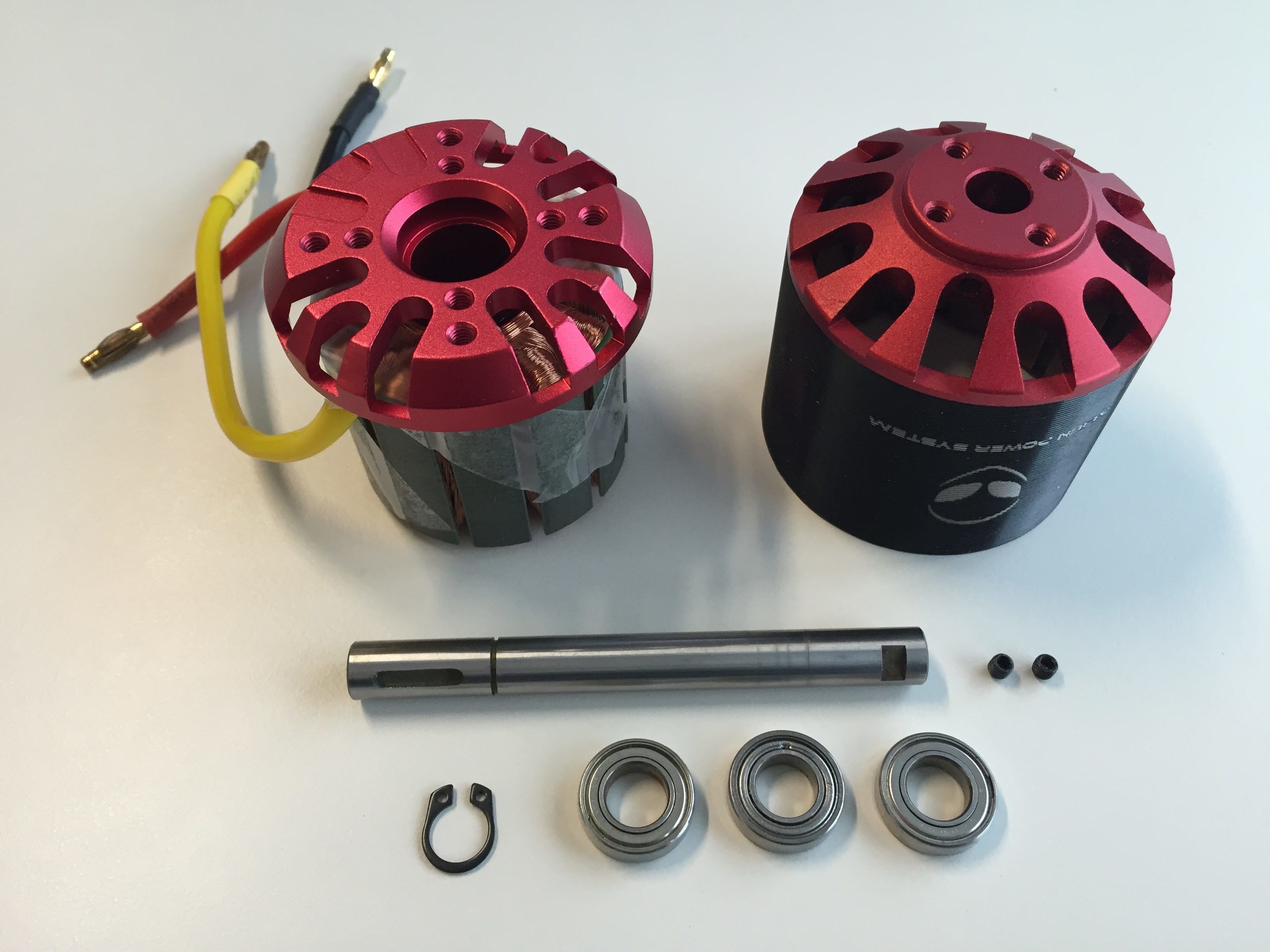
The first step I did was to convert the motor winding from Delta to Wye. How this can be done is described by @Duffman somewhere on the forum I suppose.
Doing so, the motor kV is further reduced by a factor of 1.7 resulting in 39km/h (8s, no losses, pure kinematics) with my 90mm wheels. Additionally the torque increases in the low rpm range.
Obvious to see, that compared to my first attempt there are several real ventilation slots.
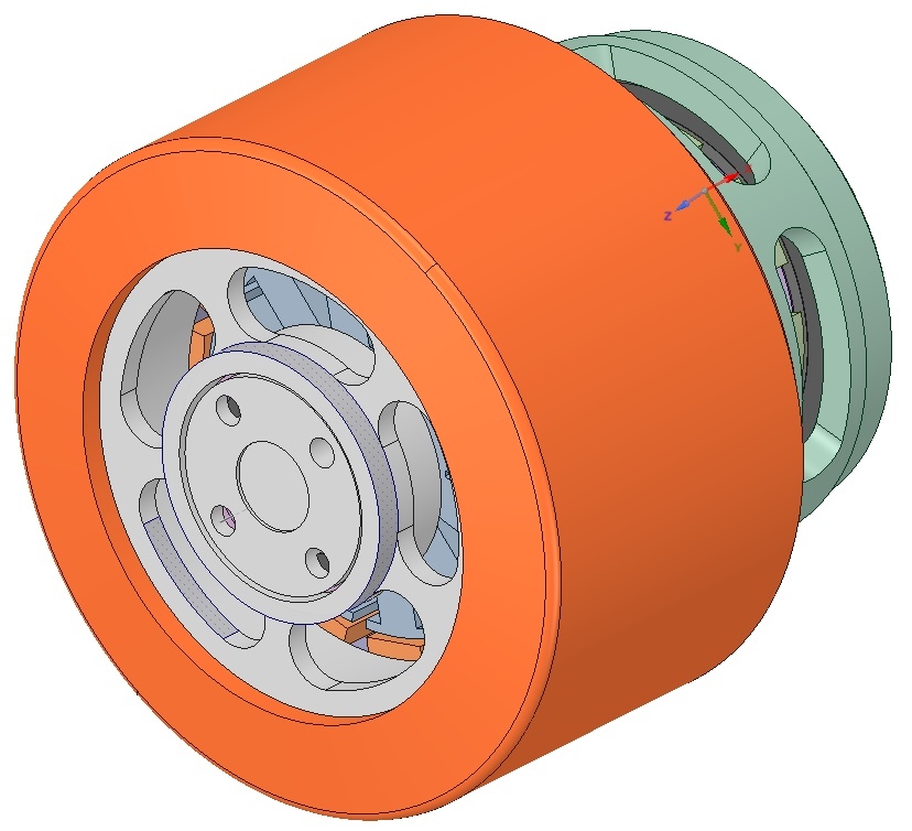
In the following posts I will describe the details of the construction and the practical issues I was facing in more detail. For the sake of simplicity here is a drawing of the cutting plane:
1: urethane wheel
2: front cover
3: back cover
4: motor can (rotor)
5: anker (stator)
6: stator insert
7: stator endplate
8: axle (cast aluminium)
9: clamping sleeve
10: mounting nut
11: circlip
12: front bearing
13: back bearing
14: screw
If desired I can also post the 2D drawings later on. Please keep in mind that they are released under the license of Creative Common License “Attribution-NonCommercial-ShareAlike 4.0 International” https://creativecommons.org/licenses/by-nc-sa/4.0/legalcode and you automatically agree to the license terms when using.
Just added some numbers to the cutting plane in my previous post to facilitate the description.
1: urethane wheel
2: front cover
3: back cover
4: motor can (rotor)
5: anker (stator)
6: stator insert
7: stator endplate
8: axle (cast aluminium)
9: clamping sleeve
10: mounting nut
11: circlip
12: front bearing
13: back bearing
14: screw
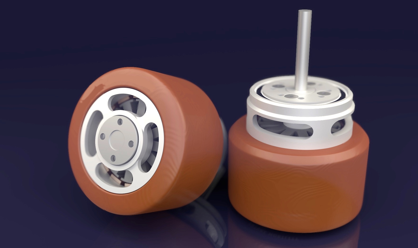
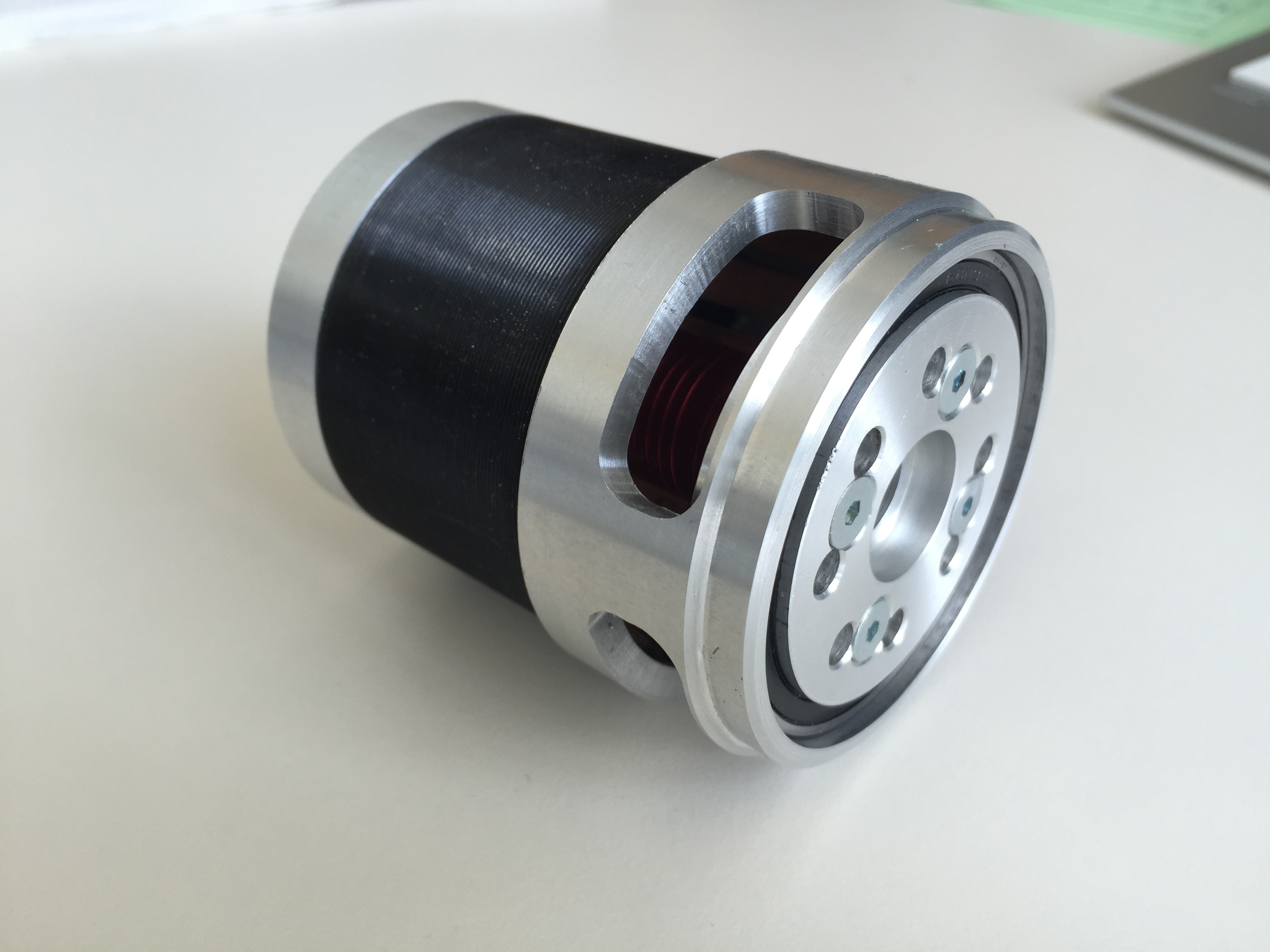
Rotor and Wheel
I wanted to move the complete motor as far as possible inside the wheel (1) to get a minimum protrusion on the back part of the hub motor but also to maintain the trackwidth. Therefore the red anodized rotor cover was completely turned off the motor can. This has to be done quite carefully, in ordern not to damage the magnets.
This opened up the possibility to make a complete redesign of the front cover (2), bearing a bigger (bigger than the usual 8 mm ones) front bearing (12) while giving it a nice looking front too. The fixed bearing (12) is held in place by the circlip (11).
The urethane wheel was completely drilled out with the diameter of the motor can. So the only way to fixate the wheel on the rotor can was using adhesive. This was the price I had to pay in order to move the motor as far as possible inside the wheel, so that there is nothing left from the former inner structure to get the inner motor hooked on the wheel. For bonding I choose uhu endfest 300 which seems to be strong but also elastic (at least until now). I read a lot in the forum about the slipping urethane issues some of you guys had so far. Imho the shiny surface of most outrunners, eventually together with a low number of “bumps” are not the best basis for a good adhesing, very durable connection. So I was lucky, that the older APS rotor cans have numerous groves on their outer surface - this is what adhesive needs. In addition to that I also sanded off the black coating on the can to a certain extend. I also thought of applying heat during the curing process to further strengthen the bonding but I didn’t. I didn’t want to weaken the magnets by applying a too high temperature. To conclude, so far I never had problems with slipping urethane - but I will keep my fingers crossed.
Now for the back cover (3) of the rotor. Normally, having an outrunner where the radial forces act on the rotating axle you have an open end. For the hubmotor you have to support the radial forces acting on the outer rotor not only from the front but also from the back. The back cover (3) which is indeed more like a sleeve, is also glued to the outer surface of the motor can. Last but not least, the back cover bears the large “loose” bearing of the hubmotor.
Back and front cover are having several cooling slots to account for the generated heat inside the motor. By the way, the front cover is also glued to the rotor but to the inner surface of the motor can.
This is how it looks when assembled right before the wheel is fitted:
I will publish the 2D drawings you need at the end of the thread . Stl files won’t be enough because you have to take care of several tolerances to get this thing running. The tolerances will be given in the drawings.

 ). But let’s start from the beginning. The deck is a Hackbrett Himmelreich (Flex 1) made in the black forest (south of germany) with Paris Trucks (195 mm), Blanc Longboard Wheels (90 mm), 2 x VESC 4.11, 2 x APS6374 3.2 kW (130 kV).


 . Stl files won’t be enough because you have to take care of several tolerances to get this thing running. The tolerances will be given in the drawings.