Ok, when I was completing my mod, there was no tutorial like this so I thought I would make my own to help out anyone else doing this. This is going to be a long thread with a TON of pictures to help anyone who is doing this out. I give the highest of praise to @MasterCho for designing this mod and helping me with my issues while completing it. Also props to @JLabs for selling it to me on the ESK8 Market. Finally, I’d like to thank This Endless Sphere GT2B thread for helping me with the battery mod. One last thing is I apologize for the terrible camera angles/quality/shadows, it is because I had to take all the pictures with my school laptop. Now that that is all out of the way lets get into this!
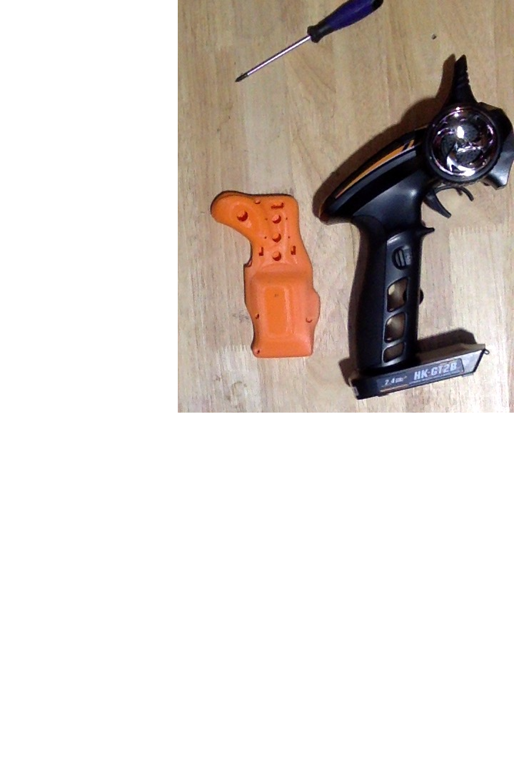
Here it is with the empty case next to the big GT2B.
The first step is to remove all the screws that hold the GT2B casing together. Just be sure to save a few of the longer ones for future use. There are some under the PCB as well as under the channel three button and the rubber wheel on the steering channel that are slightly more tricky to find. 

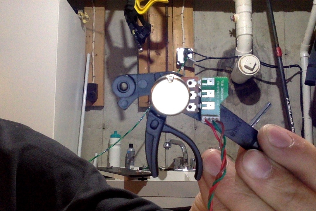
Next, disconnect the steering channel as pictured here.

Pop off the sticker with all the names for the different switches and such as well as the plastic casing around the buttons. I would keep this just in case you forget later on what they all do .

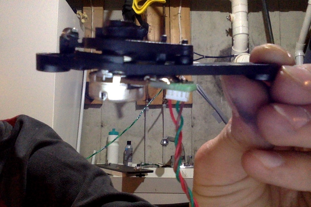
Here is the main PCB from the bottom. This is a prime example of the terrible picture angles and shadows that I mentioned before  .
.

Then you will have a small PCB on the trigger portion that you will need to bend flat.

Here is it from the bottom.
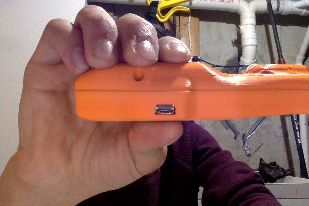
Test the fitting to the enclosure. It is important to make sure your USB port lines up with the opening in the case, this will be used for charging.

Next it is time for the battery mod. First step is to remove the sticker, I just used an exacto knife.
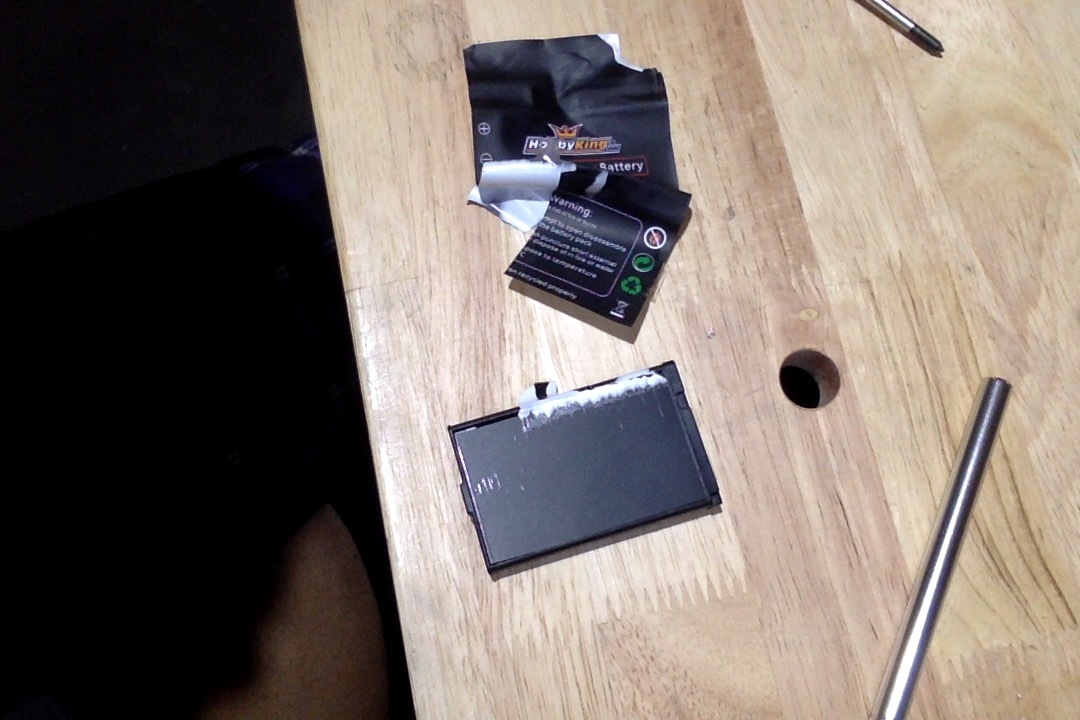
Then remove some more layers and the plastic box around the battery. IT IS SUPER IMPORTANT TO MARK THE + and - TERMINALS ON THE BATTERY RIGHT AWAY OR TAKE PICTURES SO YOU DON’T MIX THEM UP!
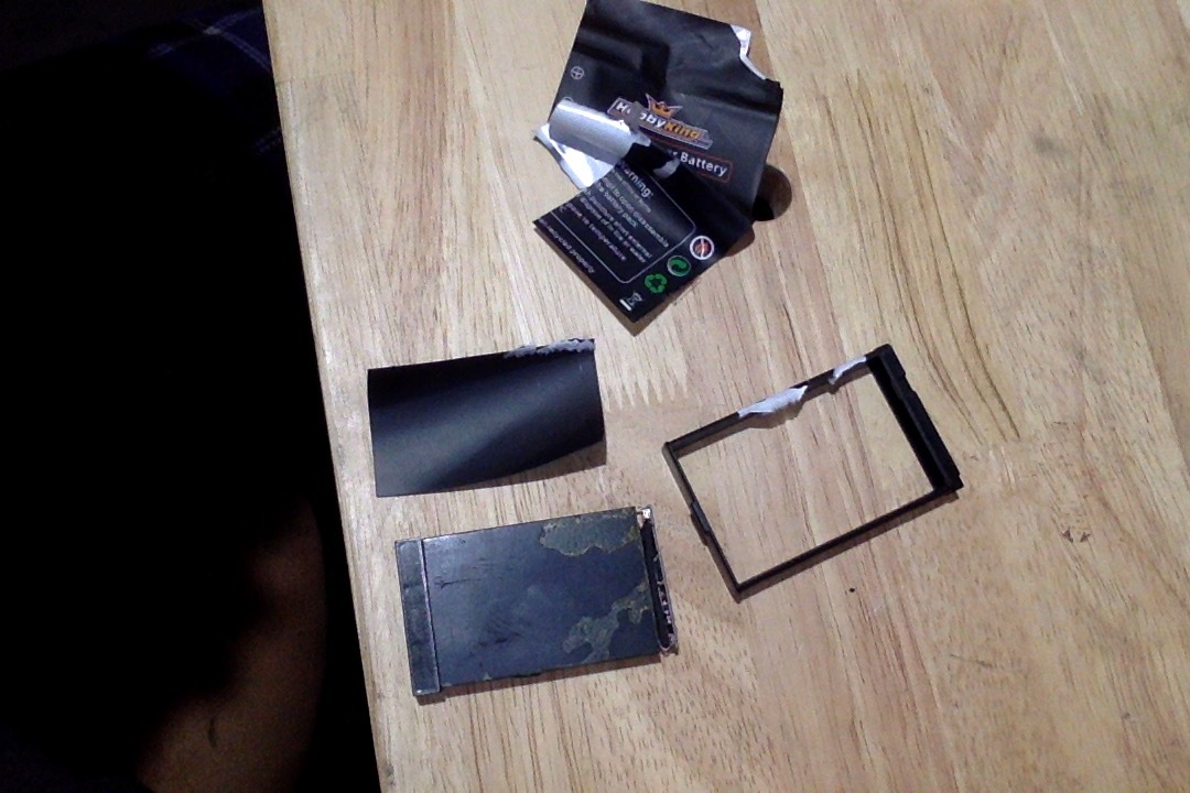
To make the battery fit, you will have to remove this piece from the bottom of the battery… I learned this only after wrapping my battery in duct and electrical tape.

Here are the wires that originally went from the battery to channel three and then to the main PCB. Do not throw these away as you can use them later.

I cut off the wire connecter that connected directly to the battery port on the PCB.

Here is where the basic soldering comes in, I am not very experienced so if I can do it, you can . Just put your fattest tip on your iron and quickly (as to not heat up the battery too much) make a pool of solder on each terminal. Then solder the red wire to the positive, and the black to the negative; you will not need the white wire as it was originally used for channel three which is gone now.

As I said before the white wire is not needed so I just cut it off to avoid confusing myself.

The moment of truth… I hook it up, flip the switch aaaaaaaand… nothing. No LED lights.

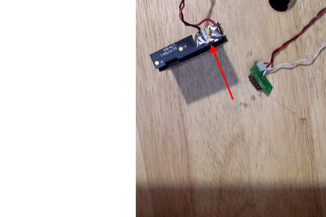
At this point I am very upset and confused. I make a thread and within in hour the mighty @MasterCho spots something unusual… Have you spotted it yet? No? Maybe the arrow will help It seems I accidentally let some solder flow onto the opposite terminal. No wonder it didn’t work. I scraped it off with the exacto knife and presto! It works! After that I just wrapped it in electrical tape to prevent shorts, as well as make it a tight fit in the case.

Now for one of the final steps, making it all fit. You will need to cut this portion off. The ideal thing to use would be a Dremel cutting disk but I was all out at the time I made this  . Instead I used some mini files and the exacto knife. They were slow but they worked.

Be careful to cut off enough to make it fit but not too much. If it is slightly too big, I do recommend some small files. It will clog up the file with the plastic but that is the price you have to pay. 

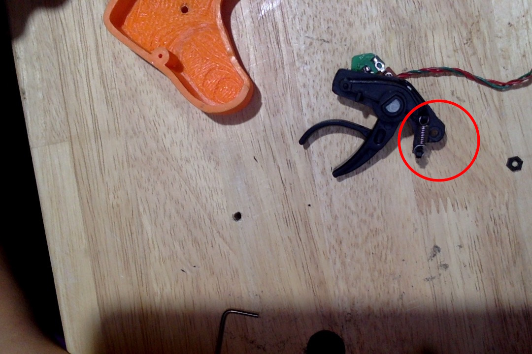
Got mine to fit. I tested the fitting in both halves of the enclosure. I also cut off a little piece that used to be in the circle I marked here to give myself some more room to work with.

Next you need to mod this hole to make it fit with the hole in the PCB as well as the hole in the back of the enclosure. I am not sure exactly how to do it so I just went crazy with a file until it fit.
Tested it with the bolt and the nut and it works! Everything is held tightly in place.


This bolt didn’t have a place for a nut on the inside of the enclose as it threads directly into one of the holes in the other side. I just simply worked it with a hex wrench until it threaded.

The USB charging port fits as well.
I was going to run to the hardware store to pick up some small bolts/screws to go in the holes around the edges until my father had an idea… why not try using some of the bolts/screws from the original GT2B casing? So I did… and they fit. I picked the longest ones I could find and they fit perfectly! I am not sure if the all knowing @MasterCho designed it like this but it is very convenient indeed. There are no threads for them in the plastic as expected so simply follow the same procedure as the bolt two pictures back. Go crazy with a screwdriver until they thread themselves . I thought it would be nice to end with a picture close to the same I started with except with all the electronics switched from the big ugly casing to the beautiful 3D printed one.

As for my last remarks, I would like to say that I followed the binding procedure in This video and it bound in less than a second. I already had the case together when I did it and I just used a toothpick to punch the bind button down. I have tested the range on the remote and it completely blew my mind. I turned it on in my basement and was still able to control my motor flawlessly through TWO FLOORS AND TWO FLIGHTS OF STAIRS! I don’t think range will be an issue with this remote . I hope that this thread will help people when completing their mods. If you are having issues with them, post them in this thread and I’m sure people will help you straight away. I don’t believe that this mod has a proper name besides “MasterCho mod” so I stole the idea of the “ChoZen mod” from This thread. If you have ideas for names I’m sure @MasterCho would love to hear them. I hope I could help and good luck in your GT2B mods everybody!
 I am sure this will help a lot of people.
Happy modding!
I am sure this will help a lot of people.
Happy modding! 
