The Evolve wires for phase leads is actually a three pinned plug which won’t be a problem as I will just simply solder the phase wires onto the three pin plug.
Probably the temperature sensor missing on the Evolve one.
Temperature sensor is the yellow wire on the Maytech connector.
Build a 6pin to 5 pin adapter skipping this one and you should me fine.
@Pimousse So you are saying that the wires is in the right order from black to red despite the colors? If so, then I can just cut off the yellow and transfer the rest over.
Good thing I have this and various other sizes. What made me go out and buy these was the VESC6 due to using larger plugs which was a blessing in diguse.
Sensored brushless motors use the same pinout as it is a standard.
Even if Evolve is this case does not comply completely with the standard using 5pin connector, I can’t see them mixing 5V and GND (see black and red wires at the same place as standard ones). A,B and C hall sensor can be mixed up, in any case, you will run a detection through BLDC Tool.
Should be fine.
Oh sorry, I was assuming you wanted to run Maytech motors with a VESC.
Well, that case, you will need to try different combinations of the 3 power leads of the motor to match the A,B,C sensors order.
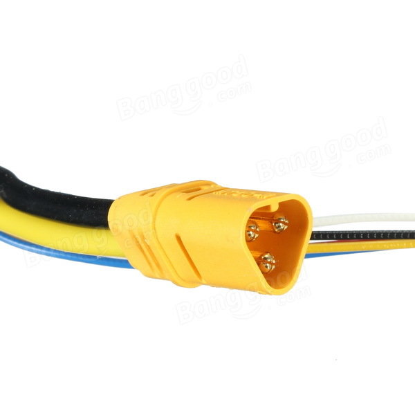
The mt60 connecter is from the old Evolve 5565 motors, I cut it off so I can transplant it onto the MayTech 6555 170Kv motor phase wires as it had bullets instead and the Evolve has mt60 connecters.
Sorry to hurt your feelings, but those are some of the worst solders I’ve ever seen.
Get a hotter iron
With a flat tip, put the iron on top of all the lumps until the solder sinks into the wire
Re heat shrink and your ready to go.
Sorry to sound like an a hole, just trying to help. Your first solder job was better than mine . Anyways, there should not be any lumps on soldered connections
@Brad
I know this is an old pos that I’m ressurecting, but I’m having trouble finding an answer. If you arent using VESC, how do you go about testing the order of the sensor phase wires to know the order is correct? I don’t want to blow my motor or esc…