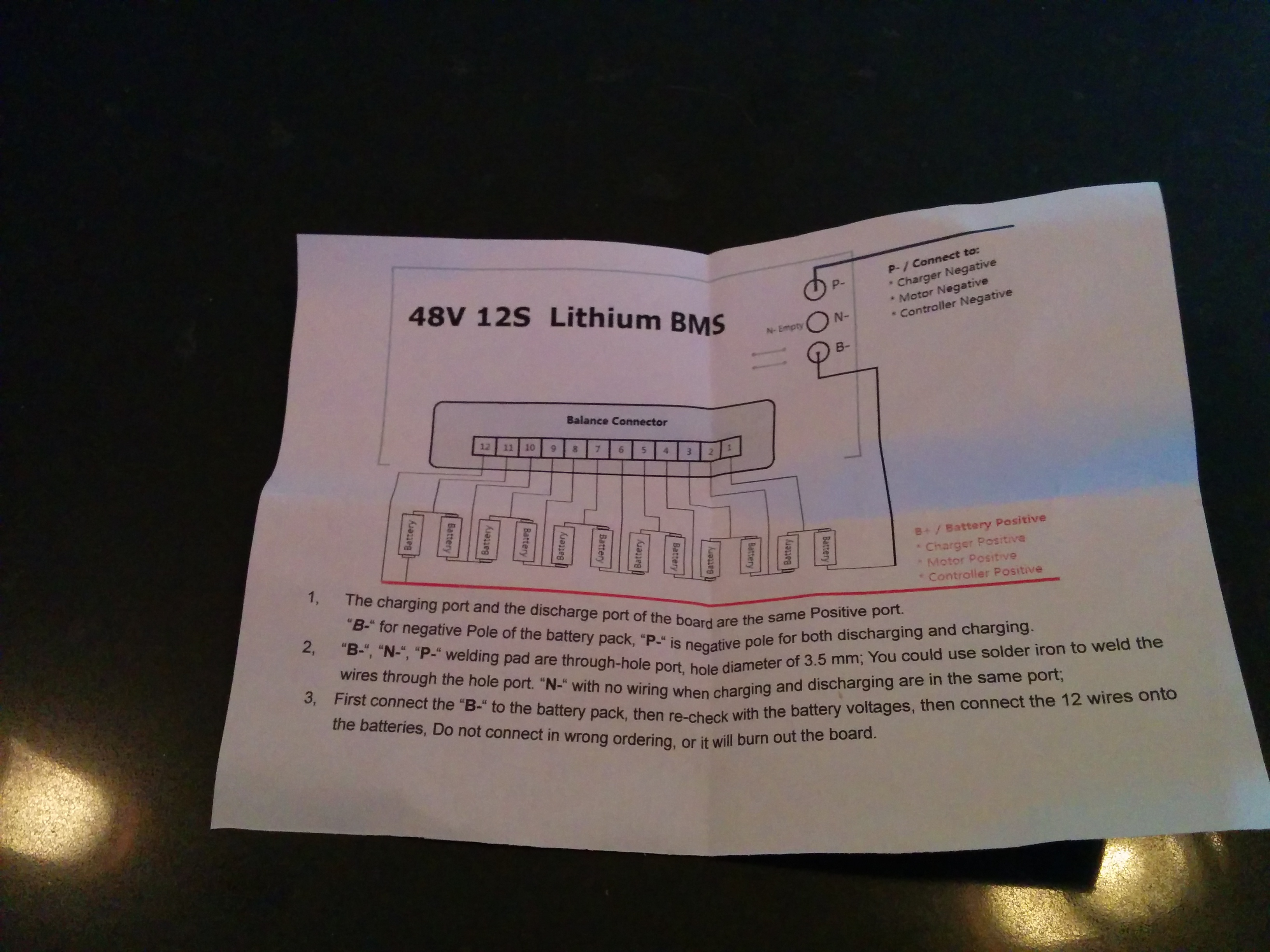
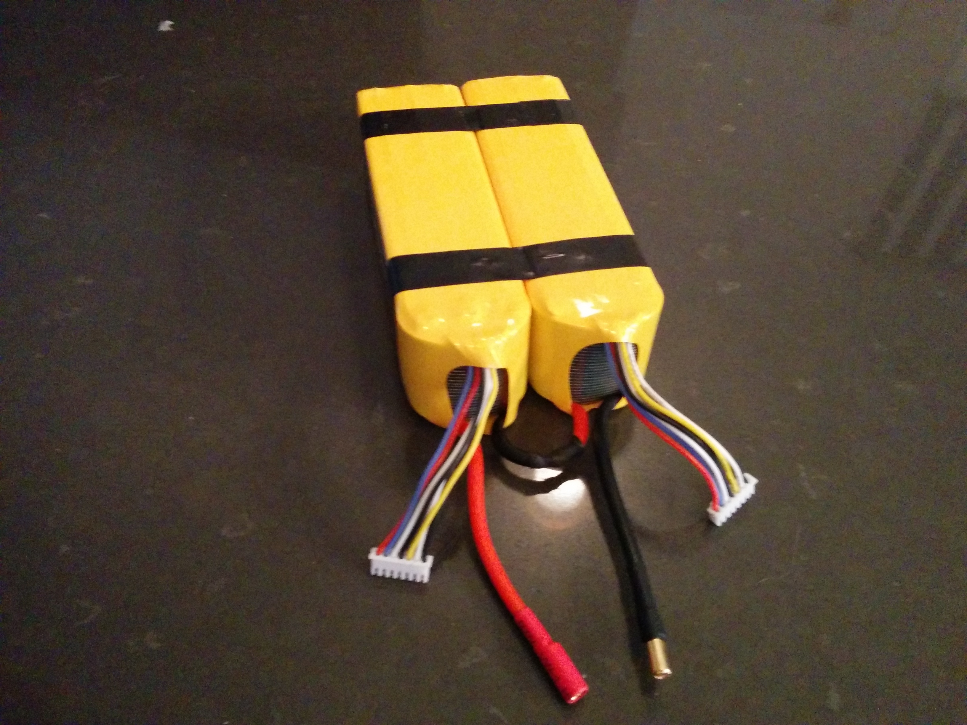
The instructions are pretty straightforward, but I was wondering how I could tell which balance lead on the lipos corresponded to whichever pin on the balance connector. Right now I have 2 6S lipos wired in series.
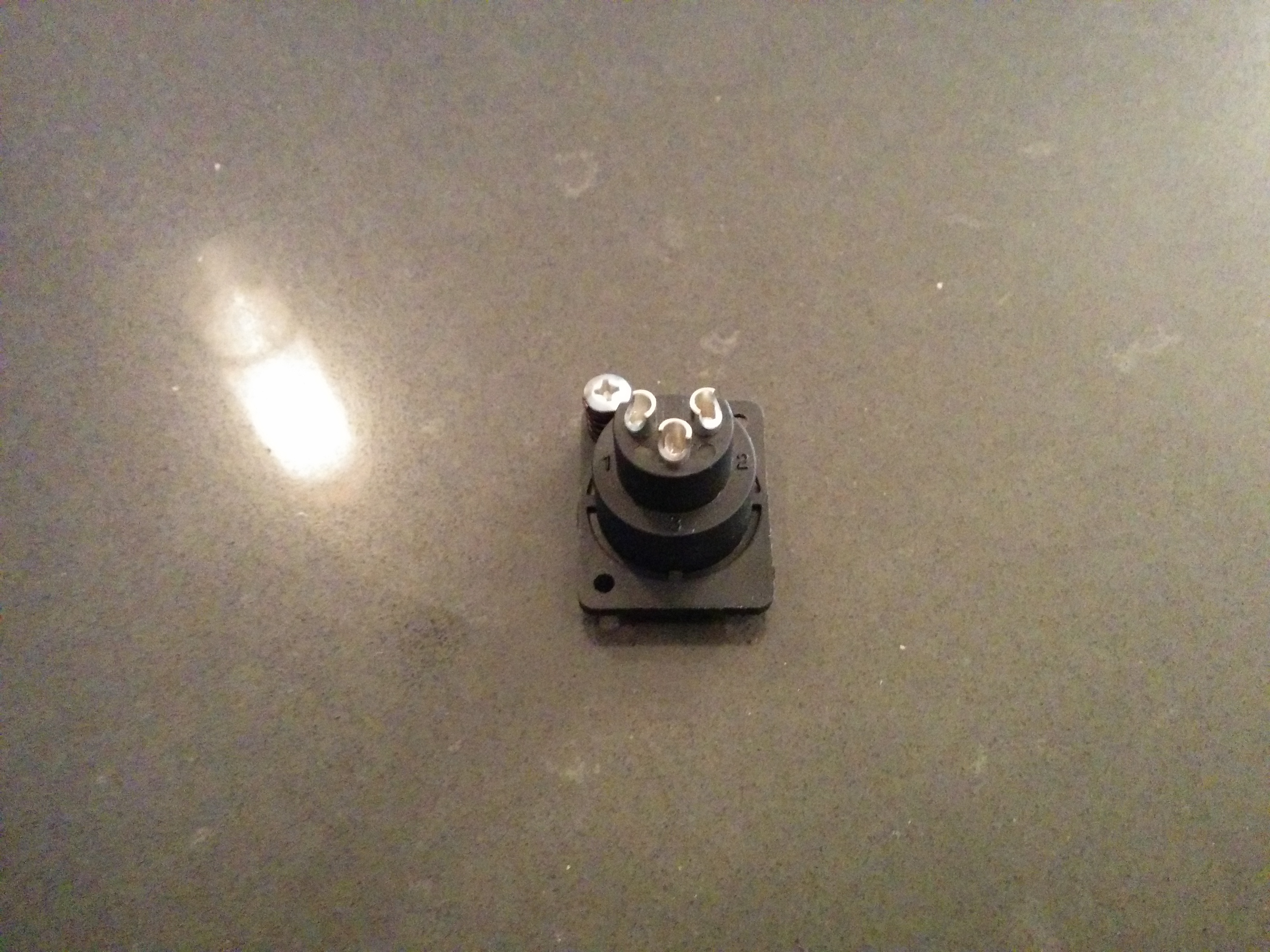
Also, The charging port I got doesn’t list which pin is negative or positive, their simply numbered 1, 2 and 3. So I’m not sure which ones I need to solder to.
I checked the voltages of each cell and I can see how they’re ordered, does that mean the first cell (3.7V) would get wired to pin 1, and the last (44.4V) to pin 12? I assume I could just cut the ground off as well.
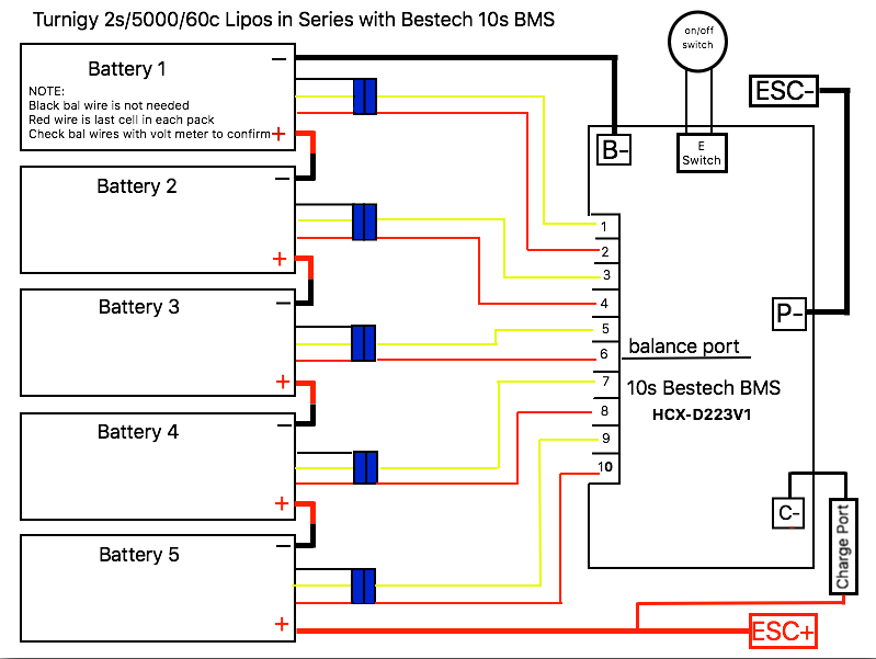
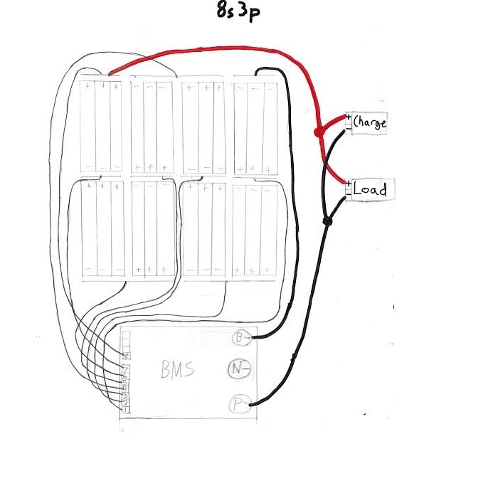
The negative battery lead is going to B-, the positive battery lead is going to the VESC positive leads, P- is going to the VESC negative leads and all the balance wired are connected.
For some reason, the VESCs are constantly blinking blue and the switch doesn’t seem to work. Occasionally, at seemingly random moments the VESCs will stop blinking and turn on. So far this has only happened with the switch in the ON position. Then if I use the switch while the VESCs are powered, they turn off as intended. However after that I cannot reliably turn them on again and they go back to blinking.
Then for some reason, when I plug in the receiver, the voltage from P- and Battery+ goes down and the VESCs stop blinking. Is this simply the idle voltage that the circuit has? Would lowering the VESC minimum input voltage fix the blinking?
Also could u tell me if your switch works? I have the same brand but didn’t ask for a switch. So far I have been using a spark connects but I would prefer a switch.
So the switch functionality still isn’t working… Does anyone actually have a Supower BMS with a working eswitch?
The voltage is staying around 2.8V which from what I’ve read seems to be fine. Presumably that means the BMS hasn’t exploded yet. This leads me to believe that it could be the switch itself that’s broken, unless anyone has any other ideas.
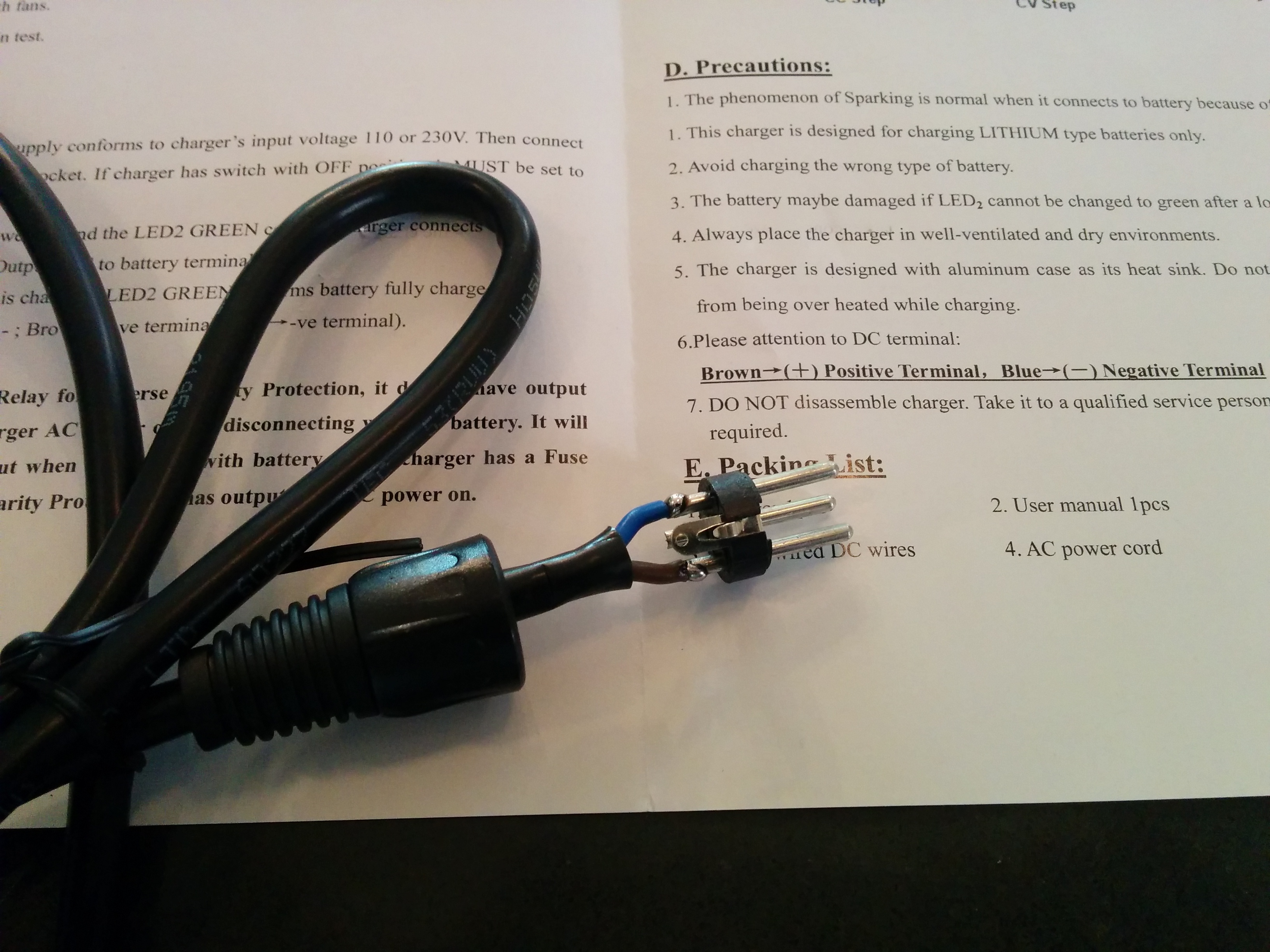
Also, I took apart the charger jack and found out which ports were positive and negative.
I’ve never seen that BMS with an e-switch. I have the same one, but use a separate anti-spark switch instead
PS. You could have figured out the pos/neg terminals on your charger, without taking it apart, by using your multimeter. A positive voltage reading between two pins means you have correctly identified the (+) and (-) pins. A negative voltage reading means they need to be flipped. No connection, or “0L”, means one of the pins is not used
i had a similar problem … the problem was that the current to activate the discharge mosfets is to low.So i bridged the activation wire from the charge mosfets to the discharge for 3 sec. So you need 2 switches 1 normal and 1 to bridge the wire for some seconds to activate the mosfets.
Cool discussion… I would have initially suggested to connect the 2pins the ‘smart switch’ is connected to… but @Fabian287 has even more knowledge… and I didnt know the thing about mosfets he mentioned… something totally new.


 But yeah if I can’t figure out what’s going on I’ll probably end up using an anti-spark.
