I’m in the process of building an eMTB with a Trampa base, Direct Drive system from @Nowind and dual VESC-X (separate topic running here), but was after some specific electrical advice here so it wouldn’t get lost with the other thread.
Qs:
How much power can I put into the VESC-X? I know a lot of eMTB builds focus on high burst lipos but is there a danger I’ll buy too much power and not be able to use it or just blow my VESCs??
Would I be silly spending loads of money on expensive lipos when some cheaper 20c would do the job if I have to restrict my BLDC settings??
Speaking of which what are the safe max settings for the VESC-X?
I have to say I’m totally useless when it comes to this side of things as I built my first board with a SPACE CELL 4 so all the hard work was done for me. I’m having to work a little harder on this one!
For motors I’ll be using either SK3 6374 149kv or 168kv and was hoping to run a 12s2p battery with at least 10ah.
Hopeful this isn’t too vague, I know I’ll also need to order connectors, and make a loop key or anti-spark so any additional info to help finish the electrical side of things would be greatly appreciated. Ideally if anyone can point me towards a complete build to learn from that would be great.
As per my linked topic above I want to ride this beast on BMX and motocross tracks so I’m mostly interested in immediate hard (but smooth!) acceleration / torque.
This is what im using atm, hopefully it may be of some use to you in your build
Im running my dual VESC-X on 12S on my EMTB for some time now. linked via canbus.
No problems using 4 x 6S 45-90c 5000mah lipos ( 2 series packs in parallel so 10000mah total)
The batteries seem to cope well and only get slightly warm when i give my board death
My motor max is set at 80 amps on each vesc using 2 SK3 6374 192kv motors.
Limited to 60000 erpm
14 tooth Pinion, 66 tooth spur and 8inch wheel belt drive
heaps of power, can get up rather steep hills towing someone on a longboard behind me lol.
Draws about 25 Amps on each Vesc at 60kmh my range is around + - 20km ish
Temps stay around 60c due to the heat sink i have them mounted on
using 4 x 1watt 100ohm resistors in parallel as my anti spark atm
But looking at the track you want to use you may want 2 x 12s car escs for more of a dirt bike feel with the lower kv motor (149 kv)and smaller pinion gear for more torque
(dont shoot me for suggesting something other than a vesc lol )
In conclusion to your questions:
1, power will depend on your gear your using in my rc experiences more c rating the better, however if you Get a higher mah pack you can have a lower c rating.
2, from the looks of it you shouldnt have to restrict anything apart for the voltage cutoffs for when your lipos are flat and maybe set motor max and batt max. for the lipos it will depend on the mah and C rating for how much power they can deliver
in theory (somebody correct me if im wrong)
a 20c 10000 mah pack can deliver 20 x 10000 = 200amps
or a 45c 5000 mah pack can deliver 45 x 5000 225amps
Having the batteries be able to burst high amps for a a few seconds is why i think the higher c rating is better
( For like starting off on a hill/on grass etc or towing a train of people behind you haha)
so for a 5000mah 45-90c pack can give you 90 x 5000 = 450a for a few seconds
over time i think it will be less stress on your batteries having a higher c rating.
3, Max setting will again depend on what gear you’re using, as long as its with in the limits of the specification on the vesc -x you should be fine
I agree totally with @Sourcecode
I’m running 60/120C 5000 Lipos in series for 10s on my street board And it works well with minimum Voltage Sag even when charging up hills.
With a mountain board, you need raw power.
The Vescs in my opinion will not be the weak link.
It seems to me that batteries are usually the weakest link.
Therefore, I like to say that it is impossible to over build the battery. My advise is get the highest C rated Lipos you can with at least 5000mah capacity.
And though it might seem like overkill, it really isn’t.
Because you need as much headroom with your batteries as you can get to reduce voltage sag, over heating, loss of power and loss of range.
I have the impression, that the higher the C rating of a battery, the more it differs from the actual C rating the battery can deliver (at least for the same voltage sag). One thing is clear: The advertised values are only valid for new batteries and get worse over the time.
In other words: It is a good idea to keep a good safety margin in your setup. Lets say the batteries should be able to deliver double the power the motors can pull, to be on the save side when your batteries get weaker.
So either go with small and light high discharge lipos and exchange them more often or take bigger medium discharge lipos for more range. It’s up to you and your riding style.
Thanks @Sourcecode, @Namasaki & @Duffman - really good information there. It’s funny, when I look at the smaller but more extreme BMX tracks I wanna ride the ability to roll actually generates a lot of momentum and I just need that added boost in between transitions to get some air! I’m proabbaly gonna end up building something with even more guts than I need but much better to have the power available than not.
Btw @Sourcecode do you have a link to that build anywhere? Really nice looking board!
I actually came across these batteries earlier which look interesting. I also think working with hardpacks like this and being able to build my own connectors would be pretty good. @duffman, I’ve posted them on one of your topics too here as I’m blown away by the swappable batteries you made and think these would do very well in a similar design.
Those are even better, as they already have the connectors build in. It was a shit load of work to build my battery connectors.
If you do it clever, you can build your board with 3s2p ‘docking ports’ for these batteries. Then you can choose everytime if you want to drive either with 3 packs for big jumps or with 6 packs for more range.
As long as you are ‘rolling’ on normal terrain, power draw should not be the problem. But if you start drifting things are getting serious…
Oh shit yeah! I suppose similarly to how your’s plug in I could just plant these face down directly on to the docks - loving your work! Hey, btw what bullet connectors do you use? Do you just solder standard 5.5mm gold ones at a right angle? I don’t have the skills or access to a 3d printer unfortunately, but I’m pretty sure I could fashion something halfway decent!
I guess I was using 6mm connectors. Not 100% sure right now.
You could just use the connectors that come with the batterys, poke them trough a piece of cardboard in the batteries, solder them on the backside and hold them in place with a huge load of hot glue, covered with a piece of wood.
Do yourself a favor and get a proper coulometer battery gauge. Not these crappy voltage based thingys. I can fully recommend the one I used in my builds. It says max 100A but I’m running up to 240A trough it without amy issues. Will post a link tomorrow…
You should also connect the balancing leads to some lipo savers to get notified if a cell runs low while the rest of the pack is still ok.
…After all the drama over the name VESC I’ve changed the title to FOCBOX as per Jason’s rebranding! I couldn’t give a FOC either way but happy to play the game
Looks like a pretty elegant solution,… but then again, costs about the same as proper energy / wattmeter duffman already referenced to and works only up to 8s.
Hey guys / @Duffman - I’m nearing the final stages of my build now and have all the components I need including the coulometer. I’ve hunted around for wiring diagrams of how to link it in and I’m still a bit in the dark. The diagram in the description just confuses me even more!
So far I have my wiring harness built from the battery to the FOCBOXs with a loop key and it works great. I’ve also just bought a 60A fuse too and it’s bloody ginormous - if I do end up blowing this it can accept up to 100A so I’ll grab one if and when it happens. I’m guessing for my fuse I can use it in place of the postive wire opposite the loop key which is on the negative wire and then join in the coulometer before the vescs? My question is can I run it directly in the loop, or do I need to run it off to one side? Sorry if this is vague, I’m not the most gifted when it comes to this side of things so any help is hugely appreciated – and if you have any pictures even better!! I’ll add a couple of pics of what I mean when I get home to make this clearer.
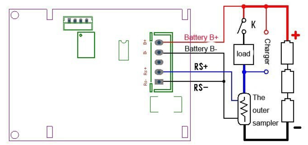
The coulometer has 4 wires. Two for measuring the battery voltage (B+ B-) and two for measuring the current (RS+ RS-).
As our currents are too big to be measured directly, we have to use a shunt (in the diagram: The outer sampler). It has also 4 connectors. Two for the power wires (the big ones) and two for the measured current (-> connect to RS+ RS-).
It is important to connect one side of the shunt directly to the negative side of the battery. The other side should be connected to the ESC (-). The ESC (+) should be connected to the fuse, the fuse to the loop key and the loop key to the positive side of the battery.
Other as shown in the diagram the B+ connector of the coulometer should not be connected directly to the battery but after the loop key. Otherwise the coulometer would always be powered and would drain the battery even when the loop key is disconnected.
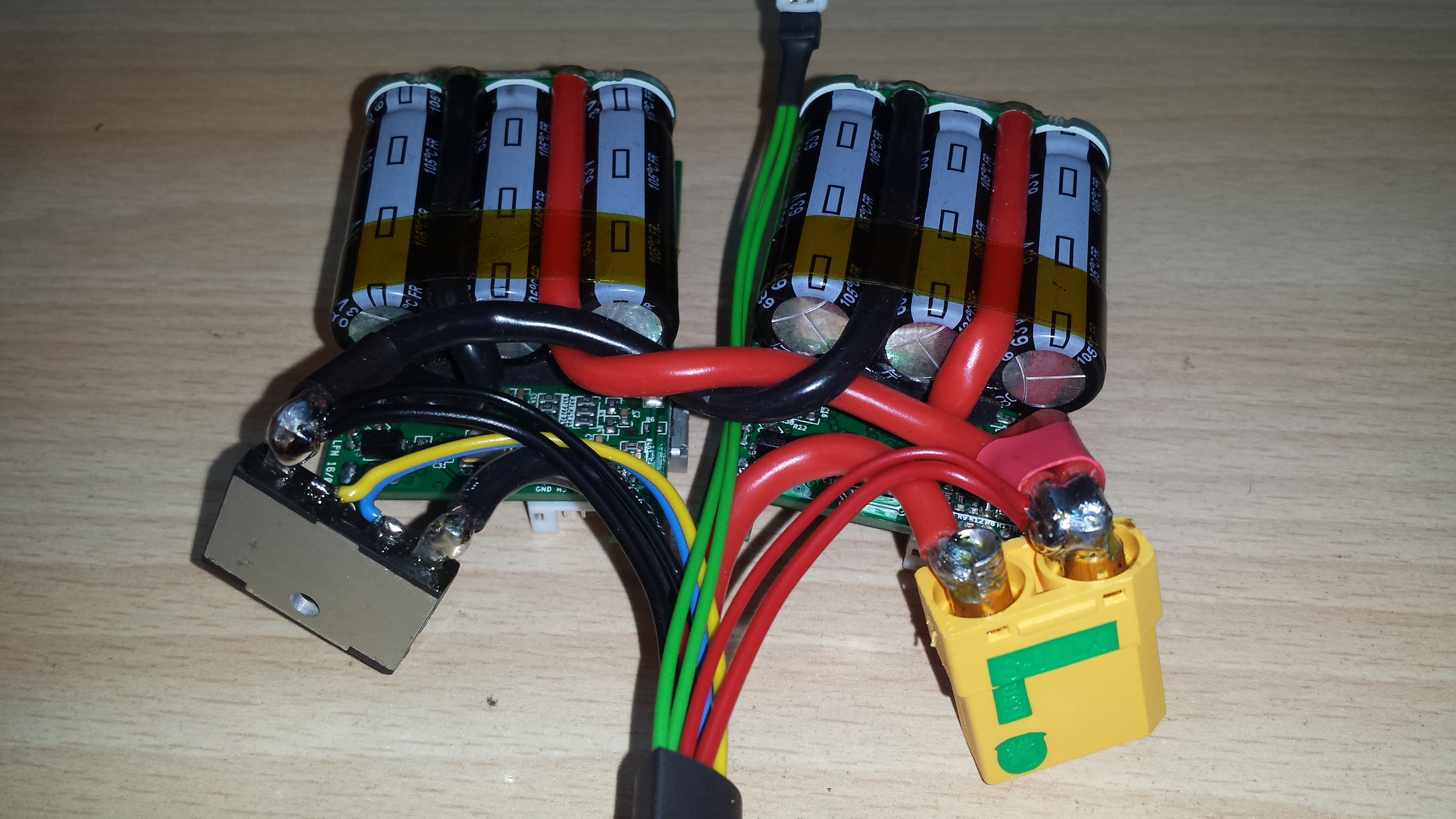
Hey @Duffman - thank you for the fast response and detailed info - I’ll look this over when I’m in front of the components to see if I can apply it. So is your shunt the black part on the left in your photo? Is that what your unit came with? I currently have a huge copper looking unit with 2 bolts:
Will this work in the same way or do I need to snip that cable?
I’ll try and get hold of one of those fuses instead and use your method as the thing I bought is a bit bloody ridiculous
So could I then run the ± wires from my dual soldered focbox on to the shunt too? So battery in on one side and my focboxs off the other? It certainly saves connectors and strikes me it’s doing the same? Thx
 Im running my dual VESC-X on 12S on my EMTB for some time now. linked via canbus.
No problems using 4 x 6S 45-90c 5000mah lipos ( 2 series packs in parallel so 10000mah total)
The batteries seem to cope well and only get slightly warm when i give my board death
My motor max is set at 80 amps on each vesc using 2 SK3 6374 192kv motors.
Limited to 60000 erpm
14 tooth Pinion, 66 tooth spur and 8inch wheel belt drive
heaps of power, can get up rather steep hills towing someone on a longboard behind me lol.
Draws about 25 Amps on each Vesc at 60kmh my range is around + - 20km ish
Temps stay around 60c due to the heat sink i have them mounted on
using 4 x 1watt 100ohm resistors in parallel as my anti spark atm
Im running my dual VESC-X on 12S on my EMTB for some time now. linked via canbus.
No problems using 4 x 6S 45-90c 5000mah lipos ( 2 series packs in parallel so 10000mah total)
The batteries seem to cope well and only get slightly warm when i give my board death
My motor max is set at 80 amps on each vesc using 2 SK3 6374 192kv motors.
Limited to 60000 erpm
14 tooth Pinion, 66 tooth spur and 8inch wheel belt drive
heaps of power, can get up rather steep hills towing someone on a longboard behind me lol.
Draws about 25 Amps on each Vesc at 60kmh my range is around + - 20km ish
Temps stay around 60c due to the heat sink i have them mounted on
using 4 x 1watt 100ohm resistors in parallel as my anti spark atm )
)