KingFisher III Build Log | Dual Focbox + APS 270 KV | Swappable 8S 160Wh / 260Wh lipo | Custom mounts / Electronics / Deck [[[OFFICALLY DEAD, merged with new project]]]

I’ll be periodically updating this thread on my build progress. Here’s a list of all parts I currently have:

Paris V2 Trucks x2 Focbox x2 APS 270 KV x2 CustomSkateboards.com deck DIYEboard airless tires 76mm road hawgs

Parts to aquire: Lipo cells x24 (8 for pack #1, 16 for pack #12s Motor brackets undecided size of middle wheel (100 ish mm. Not MBS) 3D printed enclosures Custom PCB’s and components

This board is going to be fully waterproof. Currently, I have solutions to many issues:

Motors have had internal bearings replaced with sealed ceramic equivalents. Stator will have thermally conductive high temp conformal coating. Outer bearing has an additional rubber gasket seal fitted into the motor mount, and will be greased between the seal and the bearing.

Battery case will be entirely gasket sealed shut. quick connect contacts will have a soft rubber seal to engage with the docking port on the board. The docking port will be bolted tightly to the deck using inset T nuts from the top, with a seal between. Power and signal wires to the battery will be hidden underneath the griptape in grooves. Grooves will be sealed with silicone once completed, then covered with kapton tape and then griptape over top.

Motor wires will plug into contacts inset into the deck. Heatshrink with internal contact glue will completely waterproof these connections.

Phase wires going from the ESC’s will go through the deck, and be sealed from above. Will have quick connects internal to the case to allow you to remove the case.

All wheel bearings will be ceramic sealed Zealous. Larger bearings for the pulleys for the two smaller sized wheels will be sealed ceramic.

And finally, the main control box will be sealed against the deck from below using silicone gaskets and T nuts. There is only one exposed button on this board, and that is the power button. I’ve found a fully waterproof LED button for this.

In addition, it’s using all anodized aluminum or 316 stainless steel, which is rust proof to even salt water.

By the end this board will be able to be thrown into a pool and still drive around on the bottom, and I’m not going to stop until it can do that.

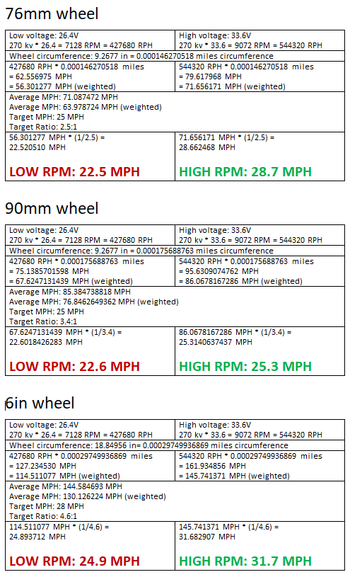
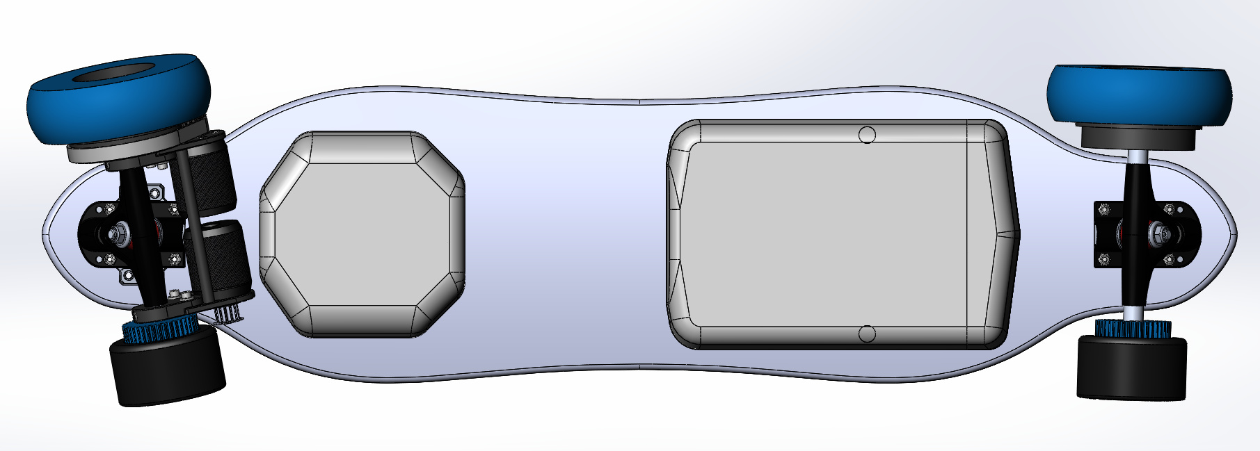
Here is a preliminary design CAD. The trucks are moved to the limit before wheel bite on the 6 inch wheels. Using 5 degree risers with 180mm trucks.
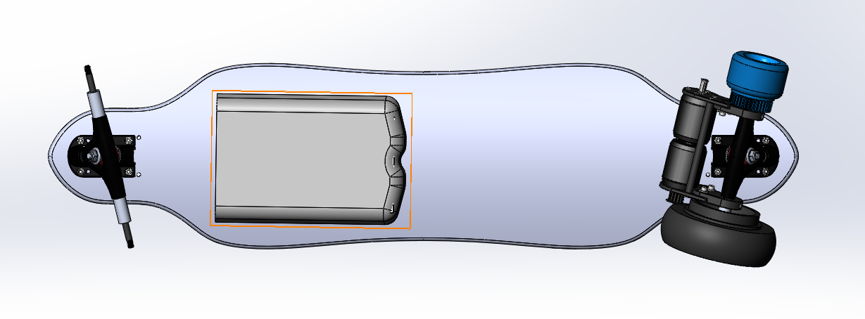
And a side profile.

Here’s the front at full tilt.

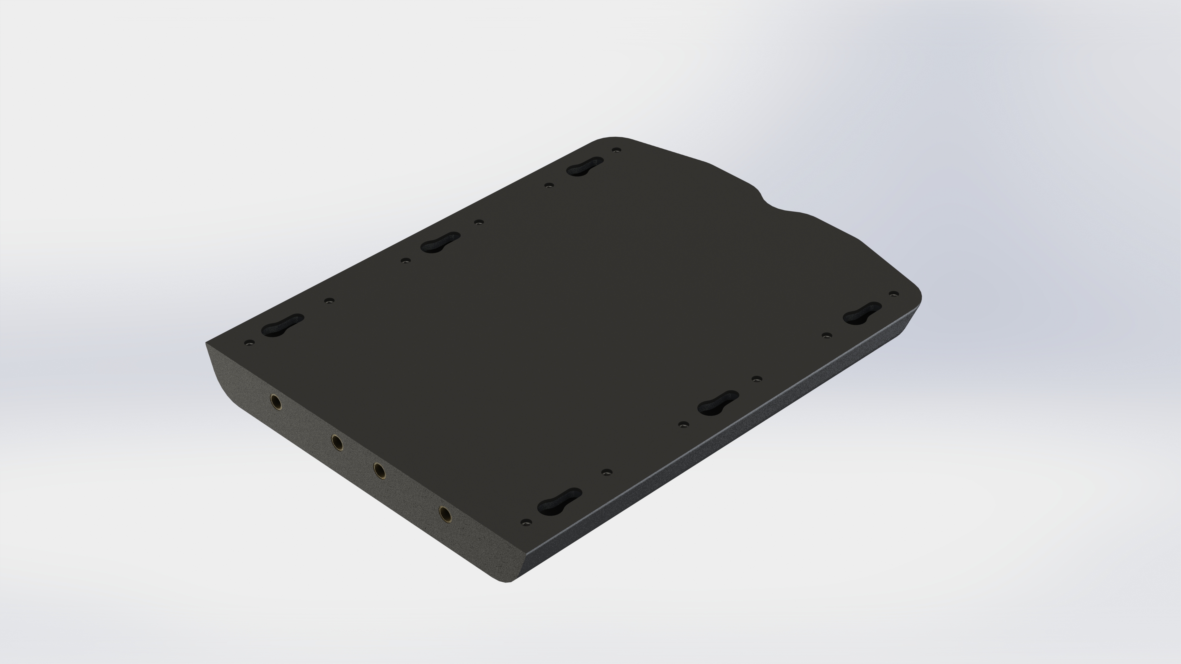
Here’s a closeup of the motor brackets.

Now I’ll talk a little about the custom electronics I’m creating (almost done with laying it all out :slight_smile: ).

Board side: Uart control of FOCbox, will read data from port

Relay controlling switching of antispark, allows for momentary switch for starting and stopping the board.

Control of underglow, headlights, and turn signals

Smart emergency stopping and unexpected disconnect control

SPI based high power NRF module for two way communication, using data encryption and packet verification

USB mini for programming / debugging

Battery pack has integrated antispark (exposed contacts are not live once the pack is disconnected) and a BMS for charge and discharge.

Remote side:

Haal effect based thumb stick control

cruise control button

turn signal buttons

Headlights / taillights switch

under glow cycling button

Digital display (can display ESC faults, temps, battery level, expected range, current trip distance etc. Contingent on software development.)

USB mini for charging, and flashing new firmware

In conclusion:

This is by far my most challenging build yet, but I’m up for it. My first build used custom mounts and custom electronics for the battery, controller, and receiver. My second build was similar.

Hopefully my third build will be enough for me, using FOCboxes as the only COTS parts. Having all my wants such as swappable batteries and wheel sizes is a must for this build.

I hope you all enjoy watching this long process of me building and machining this board as much as I will creating it. I’ll update when progress is made.

6 Likes

Impressive list of features. Going to be interesting this one. I guess you will write a custom fw for nrf control…what chip will you use ?

Currently undecided for what chipset. I’ll have a few extra PCB’s so I’m going to try ~3 different ones and test thoroughly.

As for custom firmware, it won’t be too difficult. This kind of communication protocol is very simple, using TX and RX you can cut up the data you’re sending and disperse it throughout expected data, such as specific base 16 values, which the other recieve will read and verify. If any of a string of values is compromised, that entire block is thrown out as bad data, and that one value that was sent can be ignored.

The option for data verification also is possible. The remote can signal to the board a value and a string of predetermined numbers. The board can then verify the predetermined numbers, which should match what it expects. It then reads the recieve value, and signals back to the remote the recieve value along with verification values. The controller then verifies the values, and the recieve value. It can then send another packet, which contains the next signal of the trigger, predetermined values, and a signal indicating that the last packet was valid.

If any verification values are corrupt in this back and forth process, the data is thrown out. If a series of let’s say 40 out of the last 50 packets is invalid, it senses a disconnect and will stop safely.

This kind of data verification can result in 4 packet signals of delay between input and motor change. But on the scale of high baud rate, this time is hundredths of a second. The code is very simple once you figure it out, and is plain cause and effect based.

I’d love to learn more about this as you go along. Im really new at programming (just barely touching arduino), but i would like to incorporate simillar safety techniques when i advance further with my remote.

For starters it would be great to get the vesc reaponding to my pwm signal so im a long way off from even simple uart :slight_smile:

1 Like

look forward to following this build! GL!

1 Like

For ur swappable battery I would make a hollow deck so u can make a modular battery to swap in and out, or design the locking mechanism so that you can deal with the vibrations

1 Like

Cad model of the battery swapping is almost complete. It’s very slim and will be vibration proof. All connections in and out will use 5.5mm bullet connectors to prevent any disoconnects. Slight change of plans, I’m creating a custom antispark to use a momentary switch with.

Dropping pictures tomorrow once it’s all refined.

Print nylon

E3d edge is my favorite :wink:

1 Like

Slight progress! I designed and printed some wheel pulleys for 76mm zombie hawgs. Any interest and I can release the files.

Next is the 100mm version, and the 6" wheel already has a pulley.

2 Likes

Swappable battery pack is completed. Next job is the dock board side, and the charging dock for the pack.

2 Likes

I think you’ll be the first DIYer that’s come up with a swappable battery pack. Swappable like click-in and not disconnecting XT-90s. What CAD program you using? Fusion 360?

Always a first :slight_smile: Hopefully it works well, the pack isn’t very large right now. Only 8S1P with 5000mah cells rated for 20C :man_shrugging: But it’ll be lightweight.

Using Solidworks 2017

How would you fix in so it would jump back on those bolts?

@Kug3lis The side that the battery interfaces with has a pin on each side that slides into the clearance hole closest to the plugs.

Oh ok… I was looking into something similar but the problem is 5kg or 8kg battery pack :smiley:

It’s possible. I’ve seen some that use a clip that snaps up at the end opposite of the plugs. I didn’t like that look.

Quick little update before I post some more stuff in the coming days. I’ve been sitting on this doc for a while now but I figured I’d post it now.

1 Like

Here’s a preview of the underside, I finished both enclosures. bottom

I designed a 5 degree wedge with integrated phase cable plugs. IMG_20180620_004310

IMG_20180620_004540

5 Likes

good to see someone else doing the cable riser option. What size bullet connectors are you using. Mine are 4.5mm and seem pretty robust when fitted, but there is a very small amount of slip and I’m concerned that vibrations may cause some slipage of the plugs. To counter this I propose to use some copper shim to wedge the plugs in and make them extremely tight when connected. Reckon that should do it as I really don’t want to go back to a having a thick black wire loom on show for each motor now I can see how clean the board looks with a cable riser.

Great work on the swappable battery idea as well :fu::fu::fu: