Hi I am trying to make a antispark switch (Vedders’). I would love to use a led power button instead of a rocker. Is this possible without taking power from the vesc? I can’t seem to find what the output voltage is from the switch to the button…
what about the 5V from your receiver ?
I can take power from my reciever and vesc but just wanted to know if you could do it on the switch. It would be alot easier and more modularised. As an example Miami Electric Boards has done it. (Though I don’t think that is a Vedder Antispark Switch.
Wanted to do the same, so I changed its schematic and implemented a voltage regulator that supplies the led of the button when the switch is on. Pcbs and mouser parts will arrive this week (depends if the DHL custom clearance girls have a good day or not) so I’m hopefully able to show the results in a small video very soon!
1 Like
I modified the schematic and drew the layout completely new in eagle as I’m not familiar with kicad. Dimensions of the pads and stuff might be slightly different. I also tried to make the main current path on bottom+top layer incl. vias the same or rather improve them.
Just to get this topic on course again:
I have heard from some members that they just used the normal vedder switch and soldered the wires to the + and - of the led. I have tried this approach without soldering (just holding the wires against the pins) but my led did not shine bright enough. Maybe i just needed to solder it to get a good current flow… But some people had success.
It would be good if those people could chime in here and tell their story 
You could just put an led with the proper resistor on the output of the switch
@DeathCookies do you mean that they solderd the led pins on the button to the power leads comming from the battery(e.g 10s - 36V) with a resistor in series?
@goldenHusky Good job man! Would love to see that in action. Will you release the files if it works? 
No. They just soldered The cables to two of the three soft switch wires.
Oh okey, do you know what the supplied voltage is on those?
The soft switch gets 12V from the Power supply. These 12V can be used for the LED. In my case the LED wasnt shining very bright…
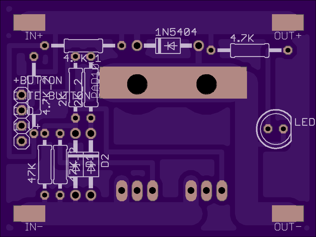
I think everyone is making this way to complex lol. On my EBoard MOSFET switch I just use two 6.8K 1W resistors in parallel to power the LED. What people don’t understand is that the LED is still getting 50V (12S LiPo) it’s just limiting the current to it. And because the higher the voltage the more current can flow through the resistors so you need a higher value resistor. Check out the schematic below and you can see the two resistors labelled as 4.7K but are actually supposed to be 6.8K that go to a output for the LED in my pushbutton switch.
Red and Black wires in the switch just power the LED inside the switch, black wire is connected to the drain of the MOSFET so that it only turns on when the switch is on. Red wire is connected to the two resistors. And blue and green are just the actual switch terminals, Common and Normally Open (C, NO)


I was experimenting with one of my switches yesterday to try and get the LED working but no luck. I discovered the NC wire is the ground and the other two have 12V. I don’t recall which wire resulted in what, but one of the positive wires made the LED light always lit when on or off…no good. The other wire made the LED light up when ON and turned off when off, but the board no longer turned on…also no good. So I don’t know, I’m pretty content with no light as long as the darn thing works. 
These are the images I found for how to wire the switch. I haven’t attempted yet. Still waiting on a few parts.


1 Like
Hey quick question, I can’t measure the resistance of the LED, but I assume it needs about 20mA (as most LEDs). But If I calculate this for 50V I need a 2.5k resistor. Which differs quite a bit from your value. What values did you use?
EDIT: Just found a 14.4V drill battery: the current throught he LED seemed to be 15mA, so the internal resistance is 960ohm. When using a 50V battery (12s liIon + I bump the current through the LED up to 20mA to avoid the led from dimming when the battery is depleted), I should need a 1.5k ohm resistor (1W). But how come you ended up using 6.8k?
So most LED’s have a MAX current of 10-20mA but they can run fine down to just a couple mA with very little change in brightness. Using a 1.5K will work but it will seriously deplete the life of the battery and will make the resistor heat up a lot more. You could run just a mA through the LED and it would still illuminate fine.
1 Like
good tip! didn’t know that. Thanks man!
Hey when I was first trying to figure out the wiring for the LED Switch I was pretty confused as well. Pretty much the + and - wires are literally just the leads for the LED inside the switch. So if you want the LED to turn on when the switch is on, you need to connect the - LED lead to, for example, the drain of the MOSFET so that when the MOSFET turns on, then the LED turns on, thats what I do in my MOSFET switch. And for the C (common) and NO (normally open) contacts, just use those as the conventional switch contacts.
1 Like