You can see the battery swap in this video at 3:05:
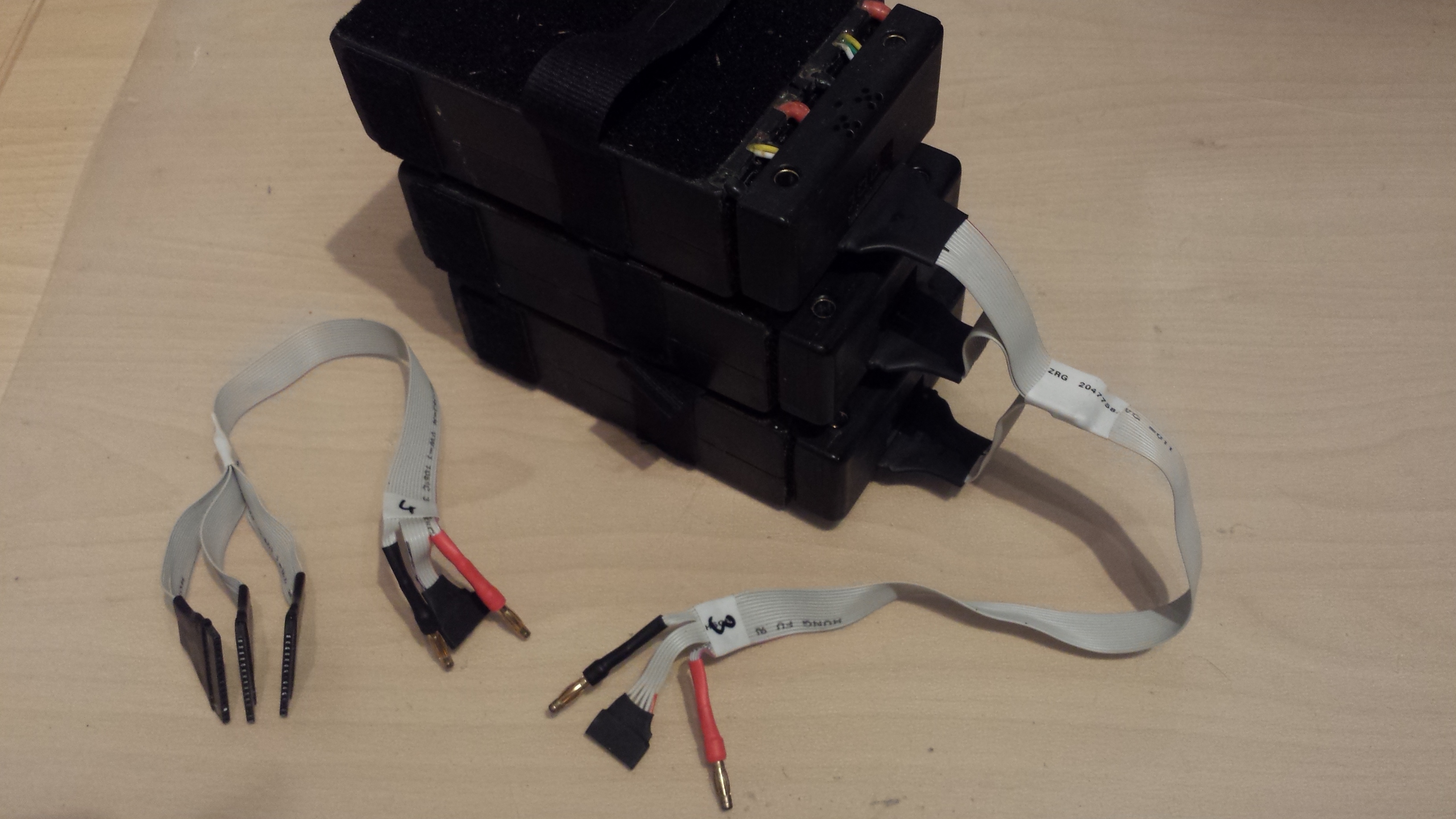
The battery adapters have an included charging port which combines power leads and balancing leads to one connector. I made 3 in 1 cables to rearrange my 3x4s serial - (12s10Ah) packs to 3x4s parallel (4s30Ah) to be able to charge it with a cheap 4s charger. I own a quadro B6 charger, which is able to charge 12 packs at once with this cabling. (4x 3x 4s10Ah)
The male to male 6mm bullet adapters sit in between when stacking batterys to increase capacity.
The ‘dock connector’ on the board consists also of a 3d printed housing which holds 6mm bullet connectors to connect the 3 individual lipo packs to series. A magnet is embedded in a slider in the middle pocket to activate the packs’s lipo saver by a reed switch when the pack is inserted.
After the first test rides I decided to mix up the parts of my boards a bit. Originally my ‘monster’ had the shorter Pro 90 bamboo deck which is lighter, stronger and has more pop. The Core 94 deck is a bit longer and stiffer.
So I took everything apart again and used the Pro 90 for the ‘race board’.
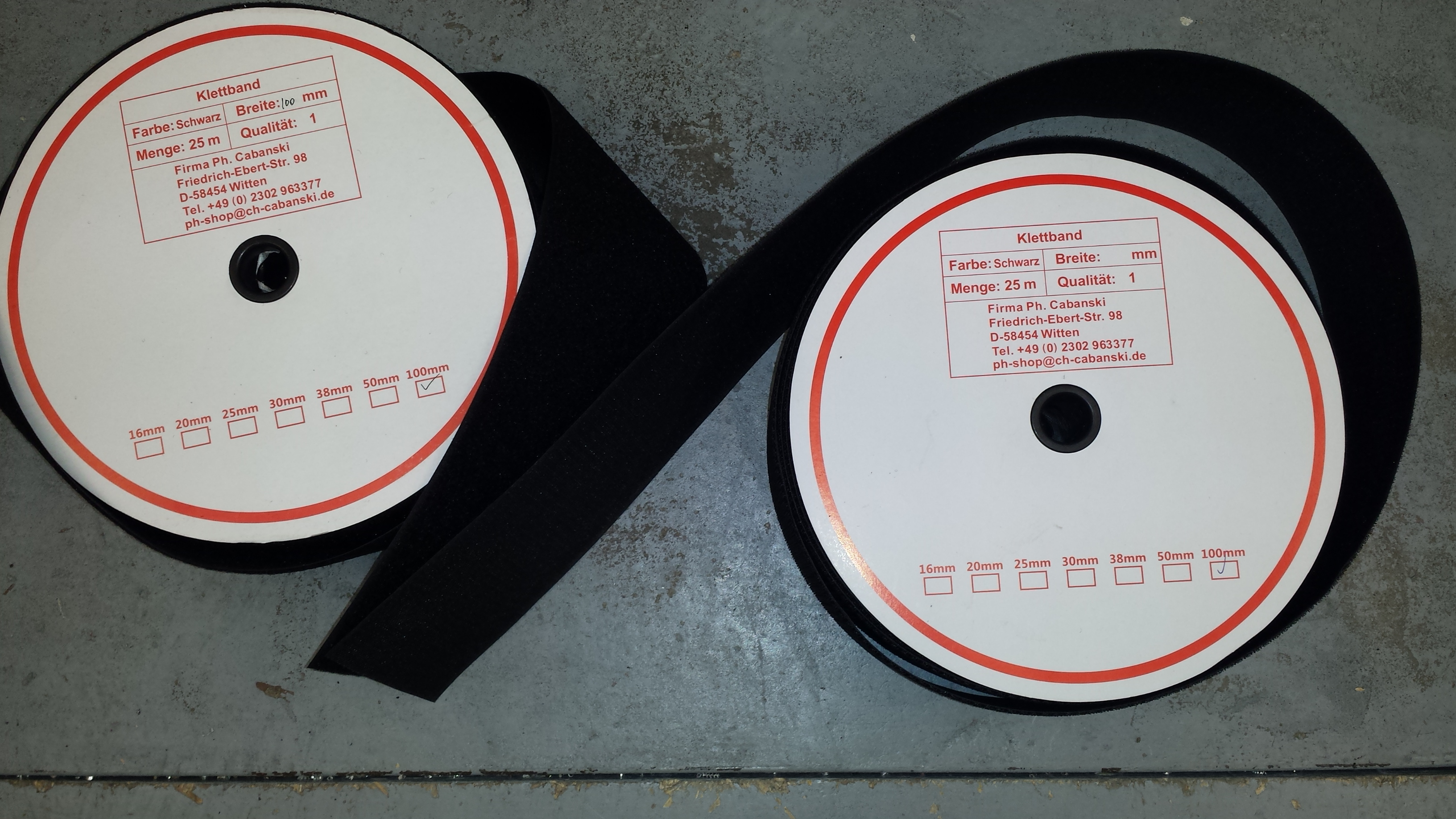
As I did not like the print I covered nose, tail and the middle of the deck with velcro to hold the cockpit, the ESCs and the batterys. The foot rests got new Viscious grip tape.
After the first test rides with this setup I had to improve a few things:
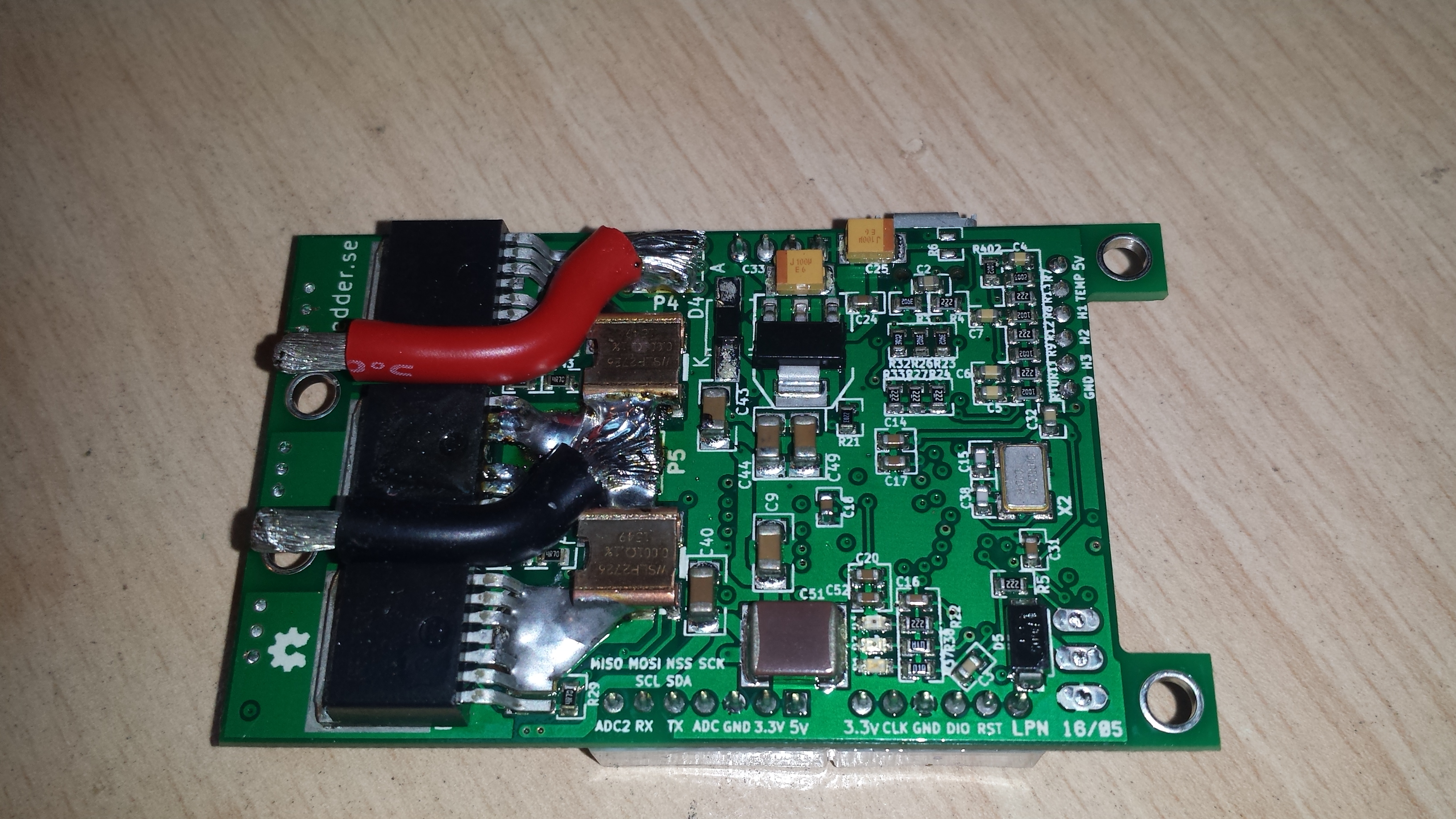
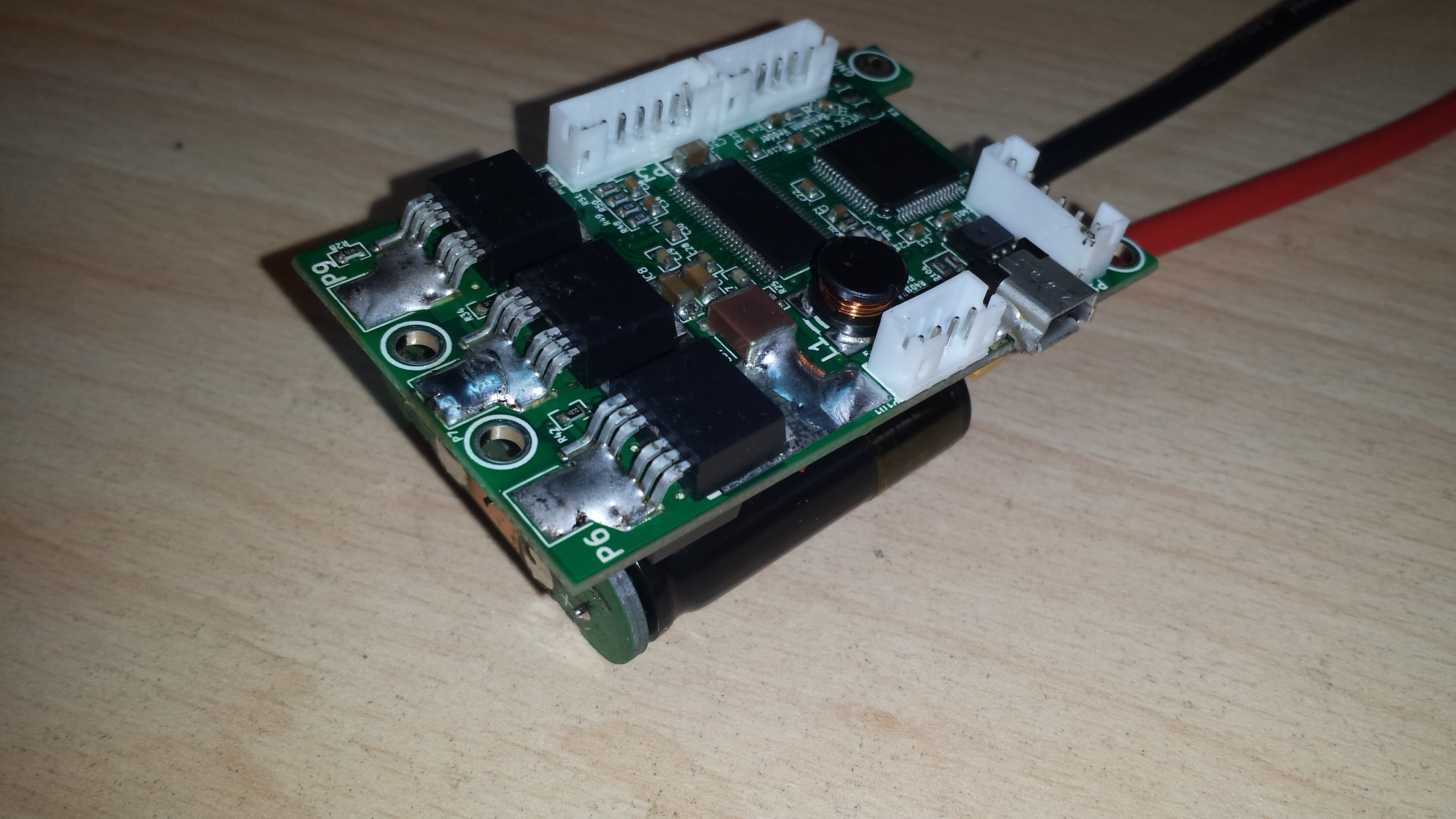
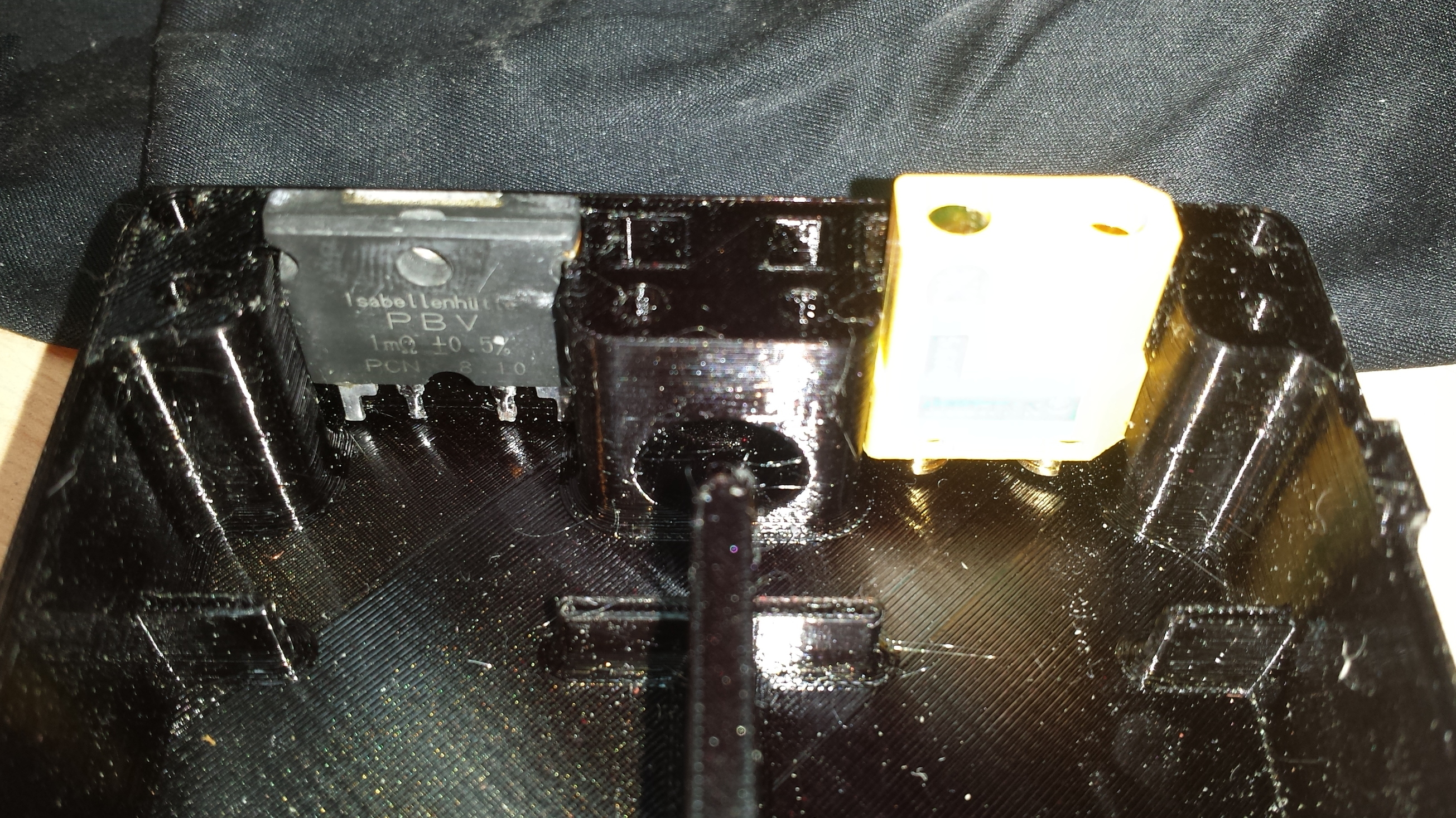
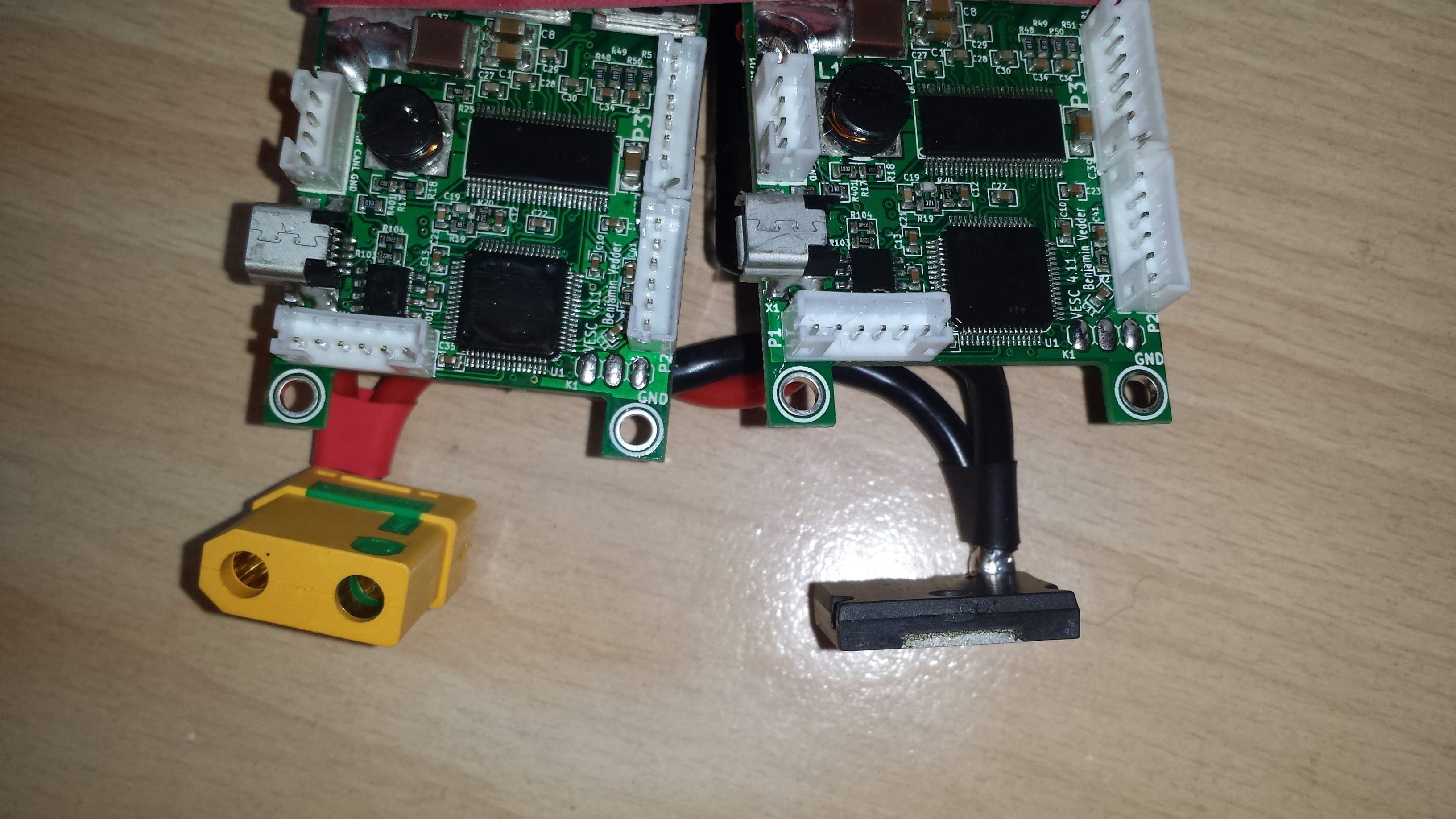
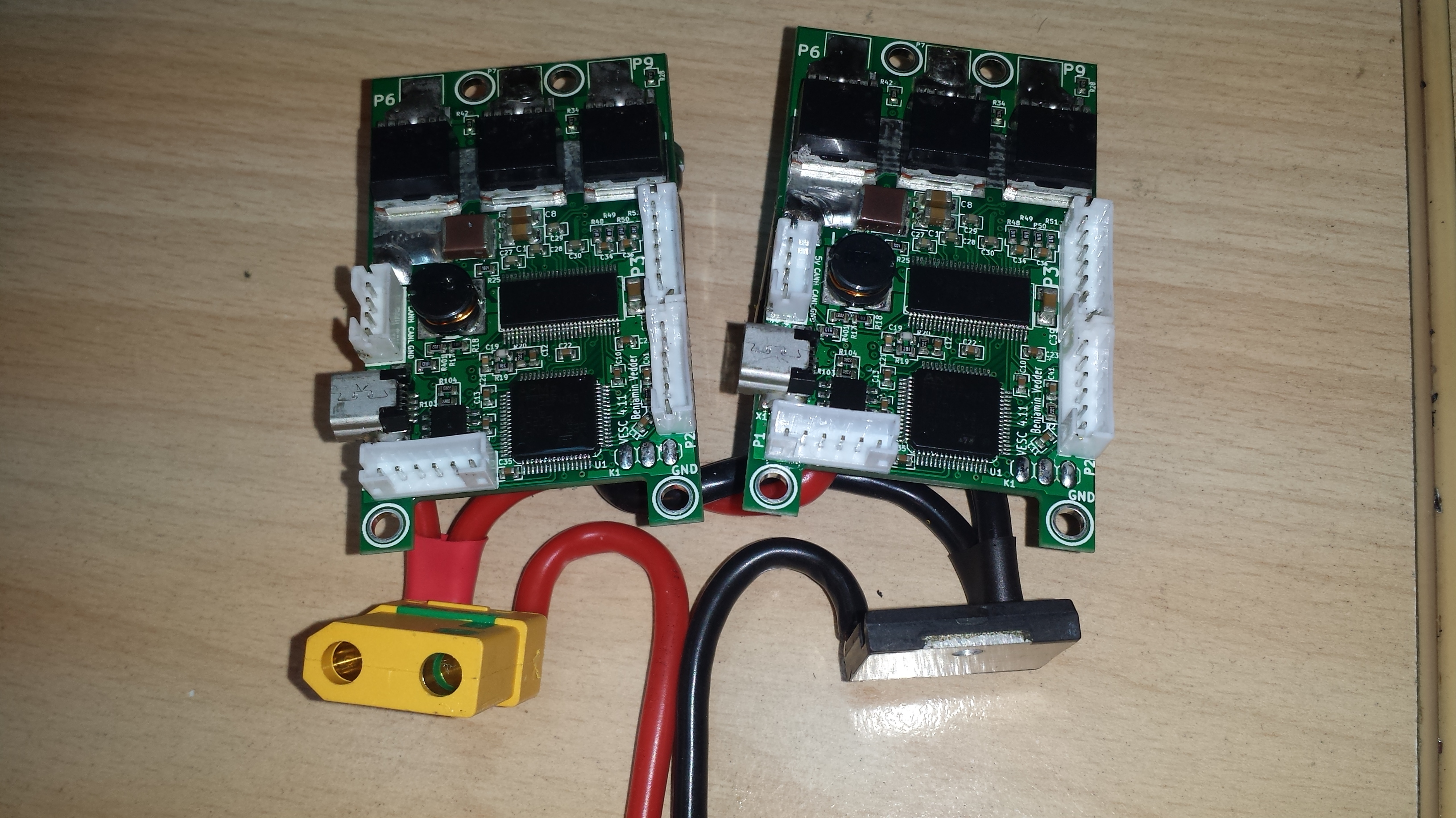
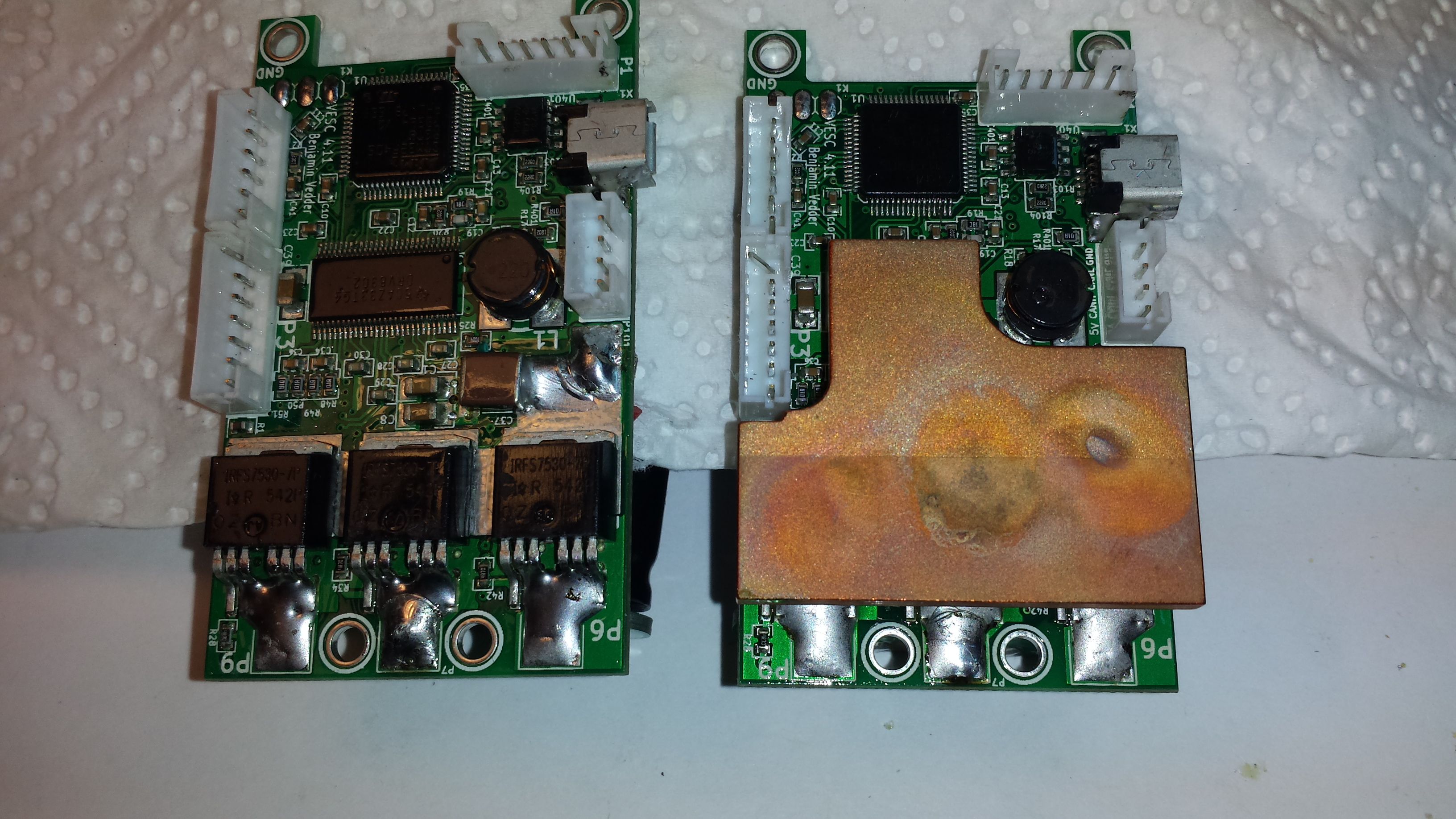
When riding hard, I hit the temp limit of the VESCs which were sitting good isolated in the small case. So I had to rewire the electronics and improve the thermal design. At first, I replaced the stock caps with ones with lower ESR:
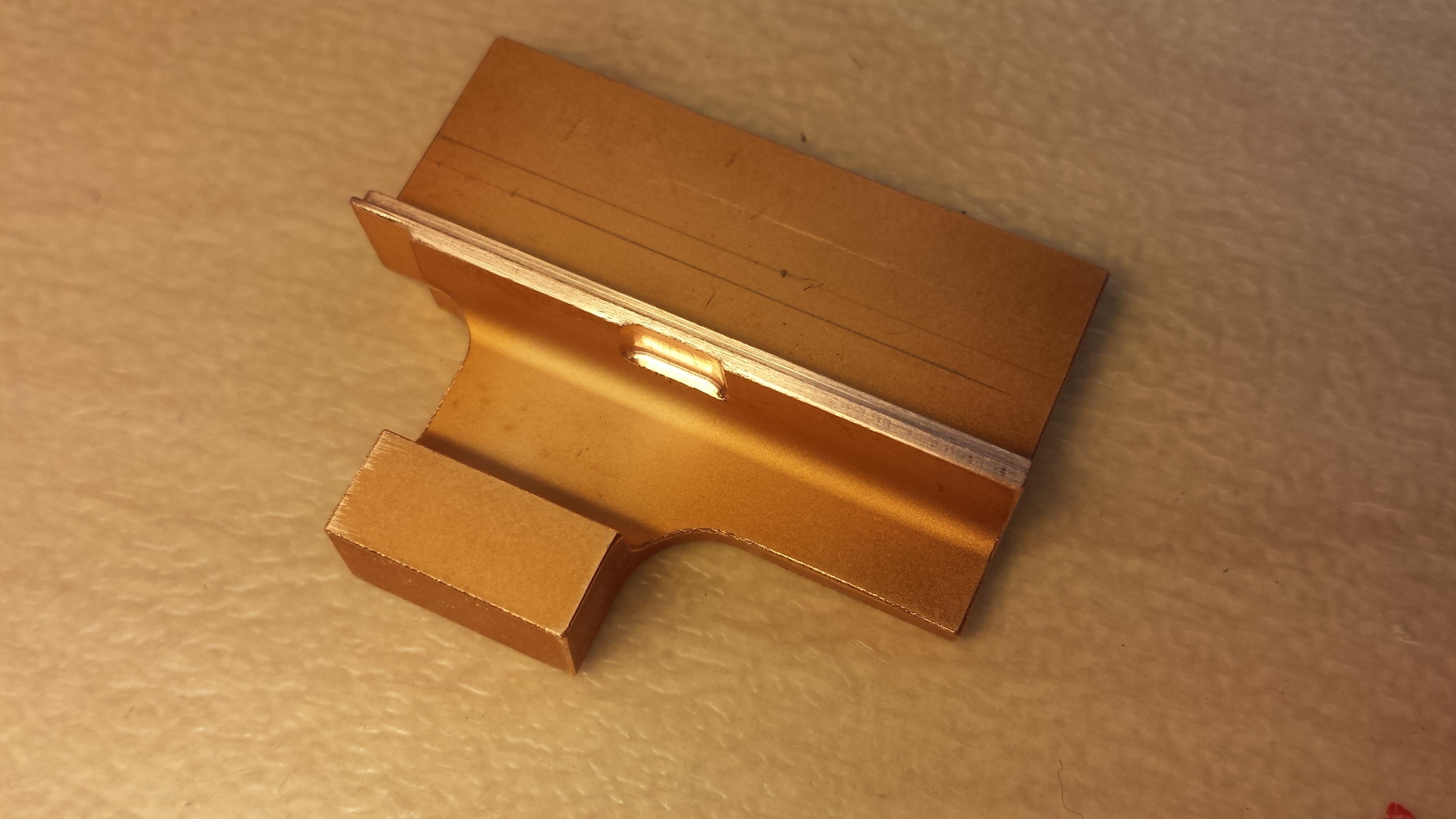
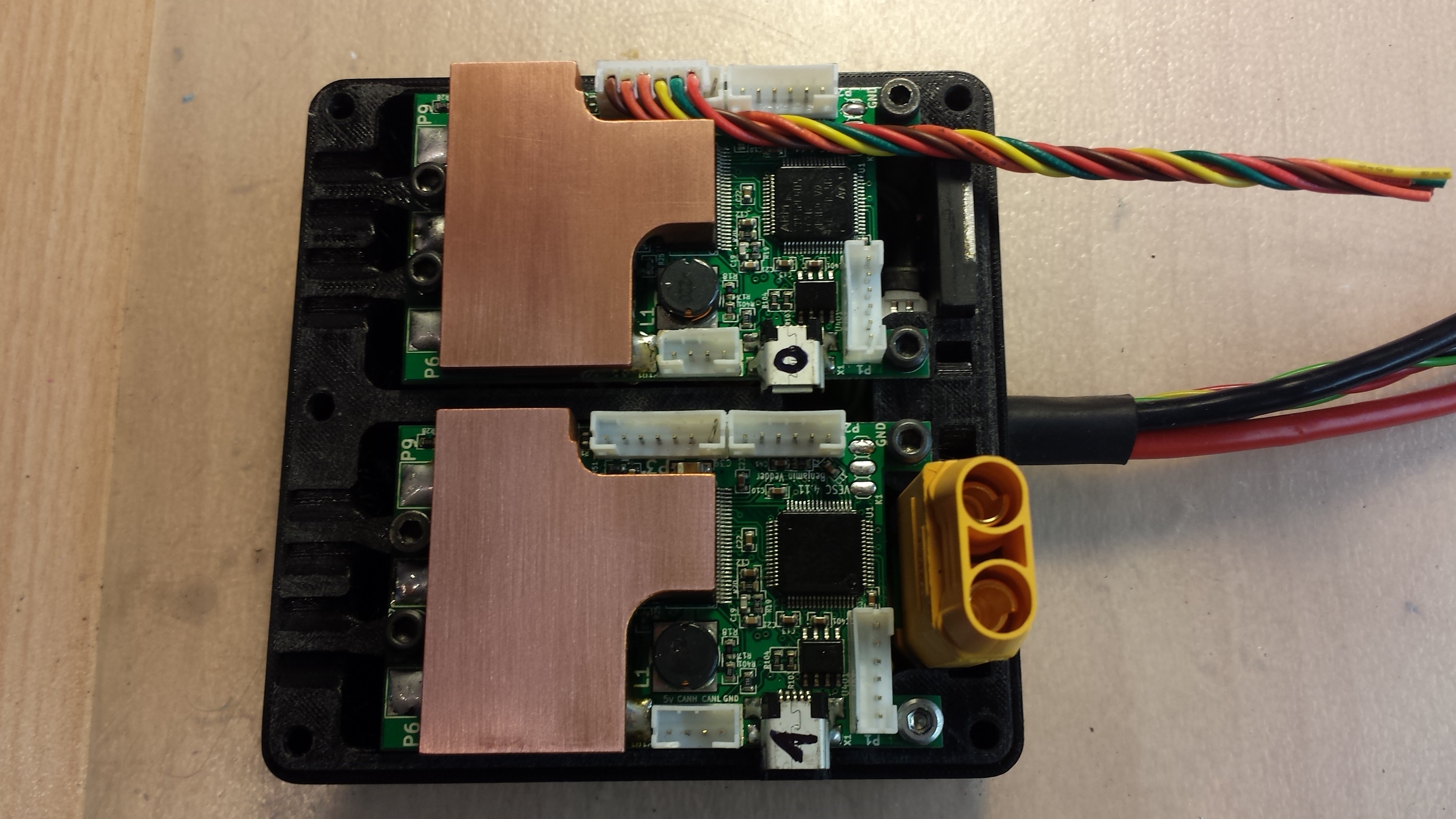
And finally topped with a copper heat spreader, which is soldered to the positive side of the FETs toget direct metal contact for lowest possible thermal resistance: http://www.thingiverse.com/thing:1853104
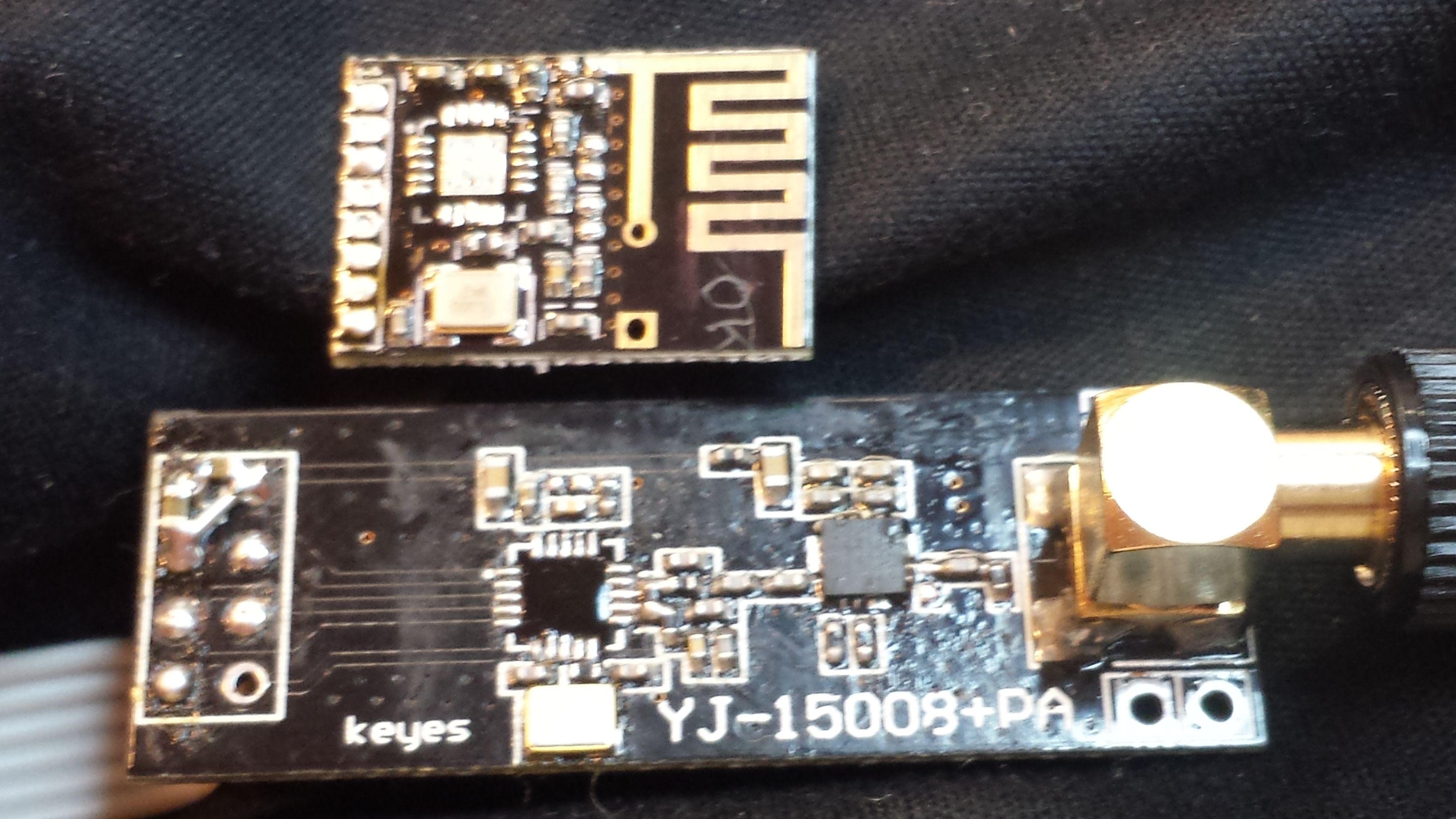
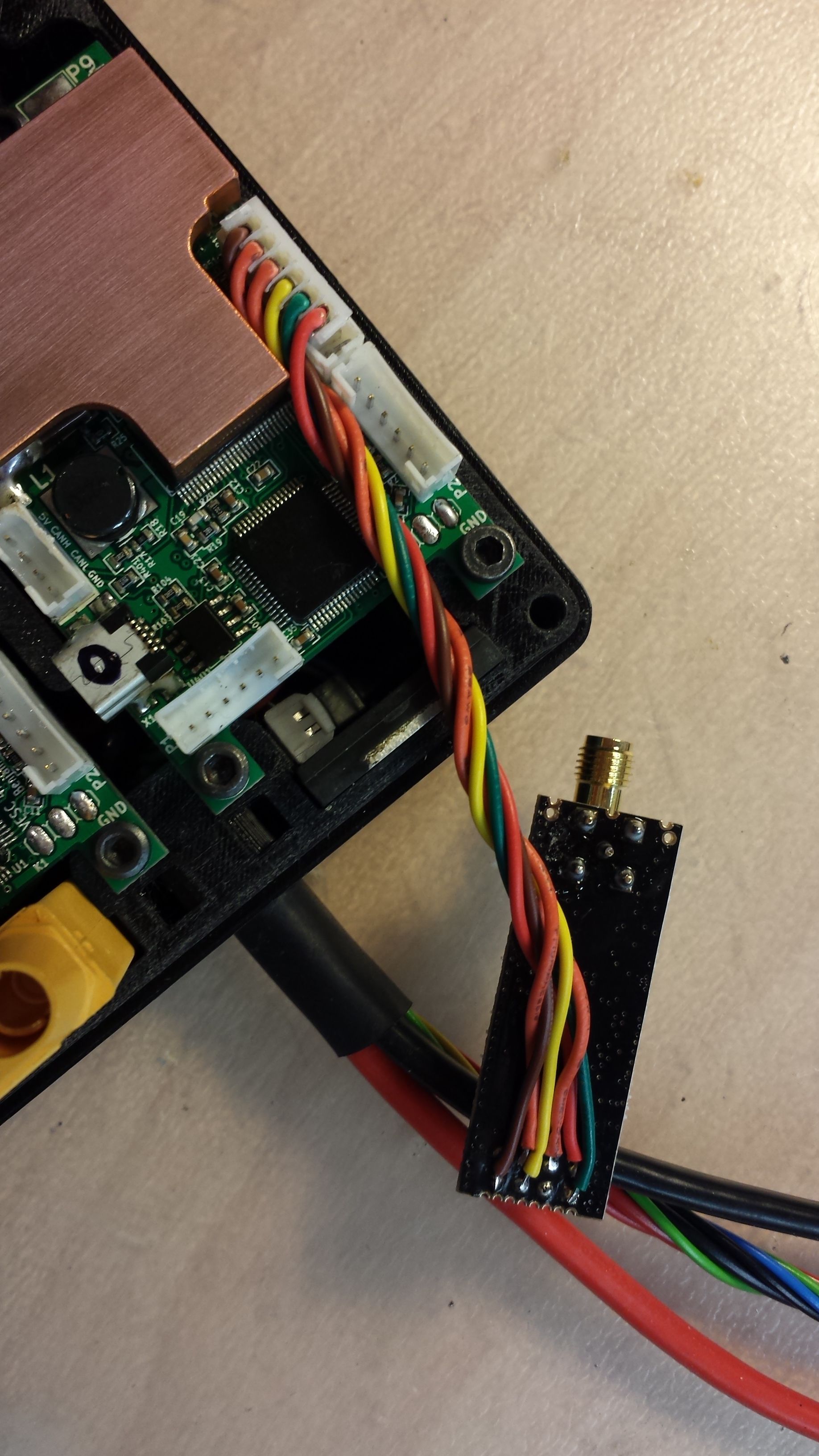
The next big improvement was the switch from the Kama nunchuk to a NRF nunchuk and later to my NRF hand controller:
The small pcb is the standard NRF transceiver, the bigger one is the ‘long range’ version with added PA. The normal ones still produced some glitches at high currents, so I had to go for the long range modules for sender and receiver.
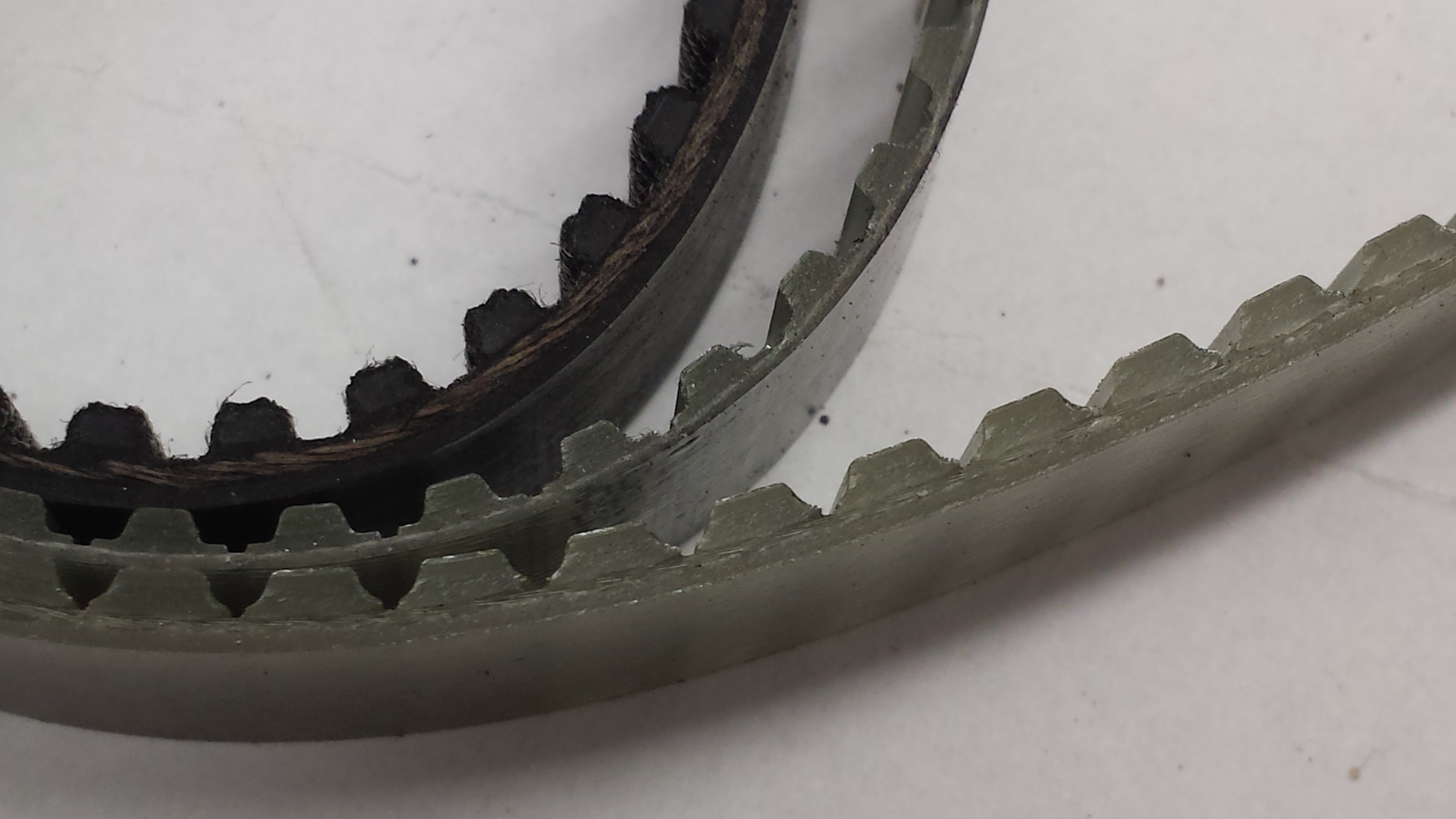
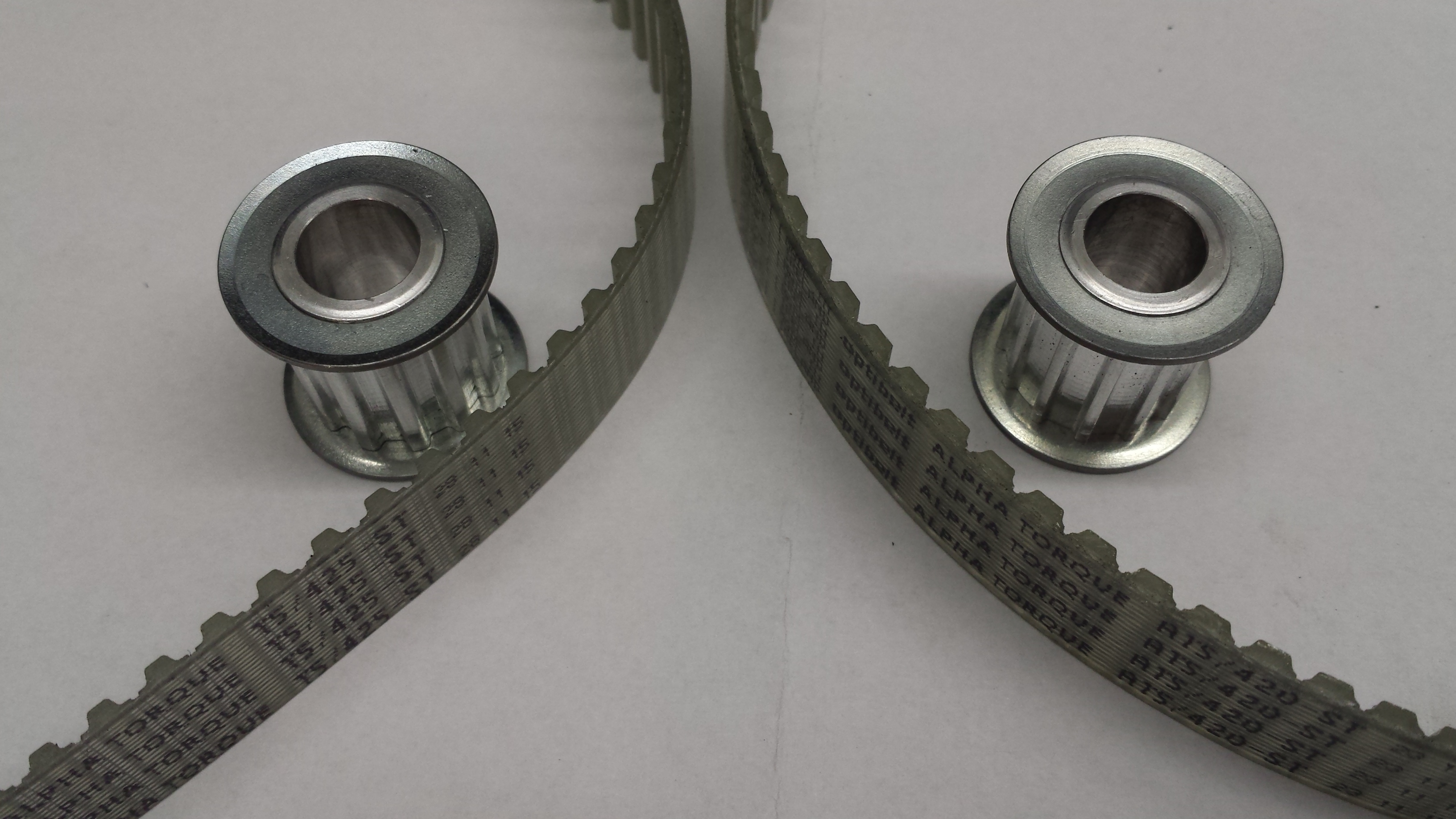
The initially used HTD5m belts in 15mm width could not hold up against the motors and got ripped every 10 km. Therefore I tried T5 and AT5 belts, which have 2x / 3x the tensile strenght of HTD. Even more important is that they don’t fail instantly like HTD, but get louder and louder, loose teeth or get spliced and remain still rideable for tens of km.
How exactly the htd5 belts got ripped apart?
Also - is it “uncomfortable” when belt gets ripped? I assume by using 2 motors u dont get to feel this as much as if u had only one motor / belt.
Did u have to upgrade teeth count of motor pulleys or the idler worked just fine for these ‘T’ profile belts? The ‘ridges’ which should grasp the belt look way more shallow than they are for Htd5 belts/pulleys
–
Concerning heat management - how big of an improvement gave that ‘heatpad’ over the fets/drv and then exposing the whole ‘assembly’ (heatpad + heatsink with fins) to the outside / wind?
Have u logged any data for this or it was just more of a ‘experience’ that fets didnt get heated up as much now after the ‘mod’?
Some HTD belts got ripped by accelerating or braking hart but some broke just while riding. With two motors you can at least ride somehow home…
I was able keep my reduction same, as the different profiles were available with the same or almost the same teeth count: HTD 85t, T5 85t and HTD 84t
The pulleys have to be replaced when you switch between the belts because they have totally different profiles.
I’ve not logged temperatures, but before the mod the VESCs ran easily into the temp limits , so around 100°C and after the mod they only barely get warm lets say 30-40°C. I’m going to add a bt module to be able to log properly…
Interesting experience you got with htd5… at what power levels were you running your board? I assume this was for the ‘‘smaller one’’ - MBS one, which is mentioned in this thread, right?
It does sound scary that a belt might break apart when accelerating… I assume it could create a nasty ‘‘snap’’ that might propel one forward as the acceleration is lost suddenly once the belt breaks…
But yeah… if the belt breaks at moderate speed / acceleration it does not sound as bad / scary.
With tooth profiles I meant it more for the motor pulley, as it is a bit smaller… but I assume this does not change much for you… as you got quite high ratios anyway… and this might be a bit worse for ‘‘smaller’’ ratios.
–
The temp difference you mention does sound like a very big / major improvement
All of that… ^^
I have a few designs floating through my head: helical gears, planetary gears, internal gears…
But I don’t think, that I will change this board. Maybe for one of my next builds…
Duffman, This build is awesome!
Im building a board now using MBS matrix trucks, but my motor mounts are not lined up correclty and also tend to loosen. These mounts youve designed for your motors on the 2wd race board are awesome!
Would you be willing to send me design files/drawings for these mounts so I can try them out?
I couldn’t find them on your thingiverse page.
I’m running 100A motor max / 100A battery max but my VESC is upgraded with heatsink and better caps. Not sure if these settings will work with a stock VESC. On my 4WD board with further improved VESCs im running 120A/120A quite safe…
Have you ever thought of using hub motors in your offroad builds? I know that they’re made for normal 83mm wheels, but after reading your thread I really wondered what you could do next.
Small (and light) hubmotors will run with low efficiency on low rpm and because of the big wheel diameter you just can’t use high rpm without gearing.
Big hubmotors would have better efficiency at the desired rpm range but would make the board heavy and would lead to other problems like mounting the tire…
This looks like the perfect solution! Very sleek and possibility of adding additional heatsink (as you did) However I don’t understand how this doesn’t short the MOSFETs. Can you explain that?