Yes I am also happy we figured out what mount I should source.
But seriously I will look into pulleys. They will habe 1 number of teeth I am assuming 36 is fine?
Yes I am also happy we figured out what mount I should source.
But seriously I will look into pulleys. They will habe 1 number of teeth I am assuming 36 is fine?
Xactly. Nobody sells them. How come you and me, Brian are the only ones screaming for someone to come with more pulley options for all this wheels. Incredible.
I prefer 38 - 40 teeth but honestly, most people want 36.
I would want a 36 and 40 option for 90-97mm and 107-115mm wheels
If I only had 100k to blow I’d buy a cnc lathe and mill and make all the stuff we need.
@bimmer, if you are going to do your homework, suggest you do it right. You need to come with the three most comon widths 9, 12 and 15 mm wide pulleys and from those you need to offer 36T, 40T and 44T and youll cover all the bases.
36T is almost like a standard…good speed and decent torque (for hills) 40T is most torque and decent speed …is like the oposite of the 36T 44T is for the extremist who want lots of torque …for lots of hills (San Fran, Denver, Baldwin, Lake Como, etc)
as for inventory and offering I could say the 15 mm will fullfil the 75% of the users needs and taste the remaining 25% divided between 9 mm and 12 mm wide pulleys.
This is way too much when probably one pulley at first will cover the biggest hole in the market right now
Yeah thats a hard no! There will be 1 and if it sells we’ll add another and so on.
Then I suggest you go with the 15 mm - 36T. That is the standard standard.
Normally what they do is producing the pulley with 1 mm extra. If you do a 9 mm belt width is a 10 mm pulley, an so on… 13 mm and 16 mm pulleys.
I got the perfect design for this. I’ve had this on hold since the runout on my lathe is too large for any precision work and it’s going to be a while before we get another…
I’ll PM you
Essentially a 2 part system that will fill all needs
I’m kinda fan of these trucks, their design allow to use a very simple mount what leads to very affordable prices 
I will put them for 29euro’s on my websop soon (truck, mount, pulleys & belt).
But what about dual drive.
Yeah that’s a problem 
Mounts
10chr
I have some on my printer I’ll upload once I go home. Basically reversable clampstyle for caliber or tb trucks.
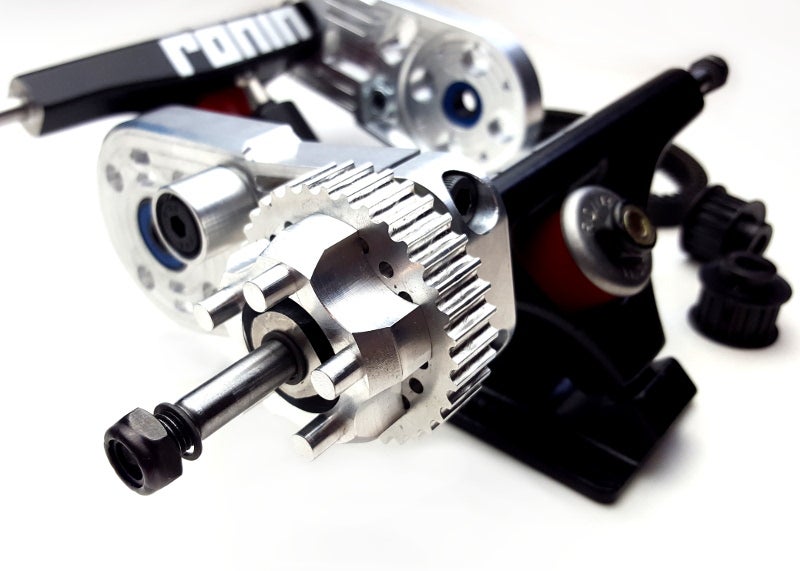
Credit where credit is due. My American brother has already designed a kick ass drive system with all the features you guys keep pointing to… yeah it has that extra bearing & it uses std width trucks hence has, faster steering response, more grip… plus what the queen pin of ronin trucks adds to no axle walk…
see that extra bearing?
no need to bolt up the pulley…
apart from drive systems I have already committed to, that’s my next drive system (and there is another out there about to come to the party I’m on board with already). Looks tough too, vented and fluted to dissipate heat as well as great design.
Ollin, JensoBro are tied with different type products, okp comes in third (sorry bro).
Can you explain this a little more. I don’t see how the bolts create an extraneous torque on the bearings.
Radial forces on the bearings?? You are applying a force tangent to the outside of the pulley on a plane perpendicular to the axle. There are no radial forces on the bearing from this. The only radial force on the system is the weight of the rider acting through the wheel.
The only reason you need 2 bearings is so that the wheel rotating axis stays in line with the axle itself and you dont get a wobble from there. A third bearing might even be considered detrimental as if the axle is not perfectly straight or your wheel core and pulley are not perfectly aligned so that they share the same axis of rotation, the third bearing would be over-constraining the assembly and applying a radial force on one of the other two bearings and bending moment on the axle. Essentially, you would have them fighting each other to keep their axis of rotation aligned with the axle and with enough time and fatigue, the axle would bend to conform to such constraints or one of the bearings will fail.
The best possible way to do it, is the way metroboards did, by placing the two bearings as far away from each other as possible so that any misalignments are averaged over a longer distance and have a much smaller impact on the system.
The wheel is slipping back and forth axially on the pulley? If this is the case then the issue lies with the spacers. The only time I have had this issue is when I bought some really cheap wheels whose core were thinner than a standard spacer width, so when installed, my wheel could slide a little back and forth until it hit either bearing. This was particularly annoying when carving as I could feel my wheels popping side to side between bearings. I resolved it by cutting down my spacer until it was the exact width as the wheel core.
That is probably the issue with the metroboards pulley. If they don’t have a spacer wide enough to sit between the two bearings without touching anything else then when you tighten your wheel, you are tightening the nut on the axle to the inner race, through the ball bearings (bad as you apply an axial force), to the outer race, then through the wheel core, then through the pulley, to the outer race of the inner bearing, through the inner bearings (bad again), through the inner race and then to the speed ring and hangar.
If they had the appropriate spacer and they might (I dont own any of their stuff) then when you tighten the wheel, the loads go through the inner race of the outer bearing, through the spacer and then the inner race of the inner bearing, to speed ring and hangar. A much simpler load path and better for the system itself.
Oh I tought you were going to produce them from metal


 these exist