These aren’t the best pics put it’s all I have right now. The idler is on the side in which the belt is pushed by the Idler pulley, not pulled.
It is hard to tell from the angle of your pictures Griff, Looks like we are talking about your mountain board w/ the motors mounted behind the rear axel?
If that is the case the jockey wheel or idler bearing should be on the upper/sky side of the mount. Is that how you have it?  Is the first pic upside down?
Going by the coke bottle in the background it’s right side up so idler is ground facing  Also upward trajectory of splashes on mount in second pic indicate orientation
haha I agree the pictures are tough to make out. They are indeed on the upward side.
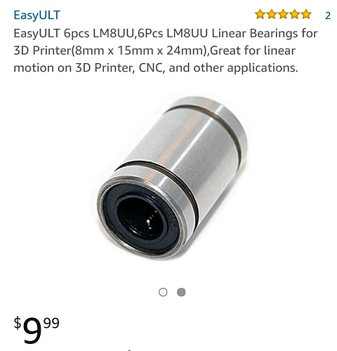
@scepterr These look like a nice solution.
Lol it’s an elegant dance between machine and human! The board is actually standing on its end and leaning against my desk.
They are linear bearings for 3d printers meant to move back and forth on a shaft, not spin around, so in this case it would not work for an islet Pulley.
@JLabs Oh that sucks, totally overlooked them being linear lol, the dimensions caught my eye @Cobber it’s 8mm bore, 15mm OD, 24mm width
15mm is pretty small, it will increase belt wear/ resistance…  It is just due to the angle the belt is bent around the roller.
bigger roller = less angle
I don’t believe any one is wrapping the belt at an extreme distance with an idler. I don’t see the few mm out of line these bearings are to cause a drastic reaction.
Read up on some engineering sites Griff, I’m also not the first to mention it. It has also been mentioned in the I love idlers thread… It is not a will it work, or won’t it work thing. But it will play in to long term reliability and the efficiency of the system. That said in a industrial setting 0% failure is often the object. With DIY most are not so demanding the odd failure is accepted and reduced life span is often the norm.
What would you say is the ideal distance from both pulleys to the idler? 20-25mm on each side??
I am very familiar with the principals of engineering and the effects of a fixed location of stress applied to the belts by the idler. My reply was referring to the fact that we only use about 15% of the bearings circumference. If the belts were wrapping around the idlers and contacting 50% or more of the circumstance then I agree the stress applied to the belts in a small area would cause much more concern.
