Hi guys. I have been loitering an planning for a while now and hopefully the board should arrive today for my build (the Pork Chop Express) anyway. I have been inspired by @whitepony to leave a BMS out of my build (partly for cost but also because I’m looking for a simple rugged build to use for commuting so the less things that could go wrong the better!
Please could someone take a look at my layout below and just advise that I haven’t made any huge mistakes? I am planning on using 40 Samsung 25R batterys in to this 10s4p layout. I will still use balance cables/plug so that the cells can be periodically checked when I take the shell off.
I wanted to make a pack that is a little more compact than laying them flat. I have thought about doubling up the cells as below. Would this also work? (dashed line on the top diagram is where the “fold” would be.
Finally I have some questions about the gauge of the balance and main power cables? What should I use for each? Plan is to stay with single drive. I am planning on doubling up the Nickel (0.25mm) on the series connector. Would this be sufficient or would wire reinforcement be better?
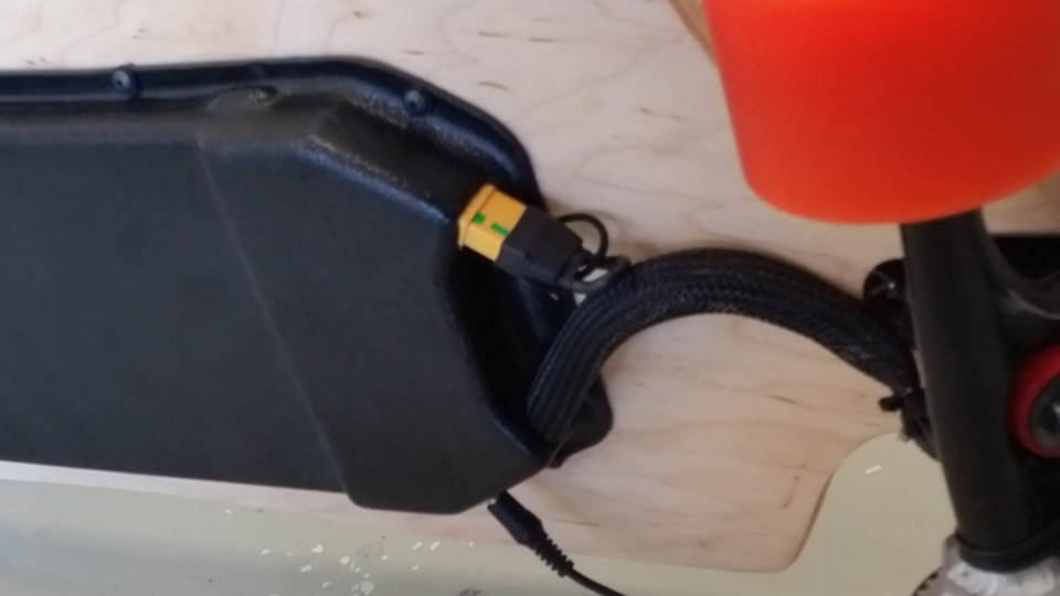
Yes that is the plan - I want to print a loop to hold/support the loop of wire as it comes out and goes back in - then I will use a spare XT90 half attached to my keys to make sure I don’t lose it.
I should also ask what I should look out for when buying a charger. I know that the Evolve one used by Whitepony cuts off at 41v is this usual? Will any 36v charger have a 41 or 42v cutoff?
Mine is wired the same way , i have the second half of the Anti spark attached to the enclosure by a strong nylon string . So i just plug in and out for my ON/OFF.
Most 36V chargers will stop at 42V, I got a charger from “MODIARY” like whitepony’s , I emailed them and asked if they could change end charge to 41V and they did without charge !
the only difference in my wiring is the Voltmeter, mine is a very small one from “DROK” it has 3 wires,… 2 for powering it, which are tapped onto the wires powering the “Reciever”… and 1 wire reads the Battery Pack V on the POS side
Yes I was planning on positive terminal rings and hot gluing the packs together. My deck should be very low flex so hopefully this will be enough to stop rubbing.
I am hoping to ABS heat form an enclosure which I will do once I I have properly planned the battery / vesc etc layout. Having seen how low @Randyc1 rides with one layer I may have to follow suit. (otherwise Ill be top mounthing on a drop thru)
I actually think I might have one of those from my drone building. Was a voltmeter rather than a battery % but maybe that would be a way to go. That is 3 wires so would be wired same will have to check it is a 5v to power it.