I bumped into Vertigo’s caster board (Endless
Sphere) a while back and thought that it looked like a very cool project. Not so sure how well this thing is going to perform but that’s part of what makes it interesting, I guess. Also wanted to get into machining aluminum so this seemed like a good project for that. Did not want to deal with custom battery pack so will be using lipos. Wanted to keep the cost down so decided to go with a wood deck although I really like Vertigo’s design with the carbon fiber and custom battery. Keeping the gearing / voltage the same as my other rig since I’m happy with it. Hats off to Vertigo for his excellent engineering work and for posting his designs.
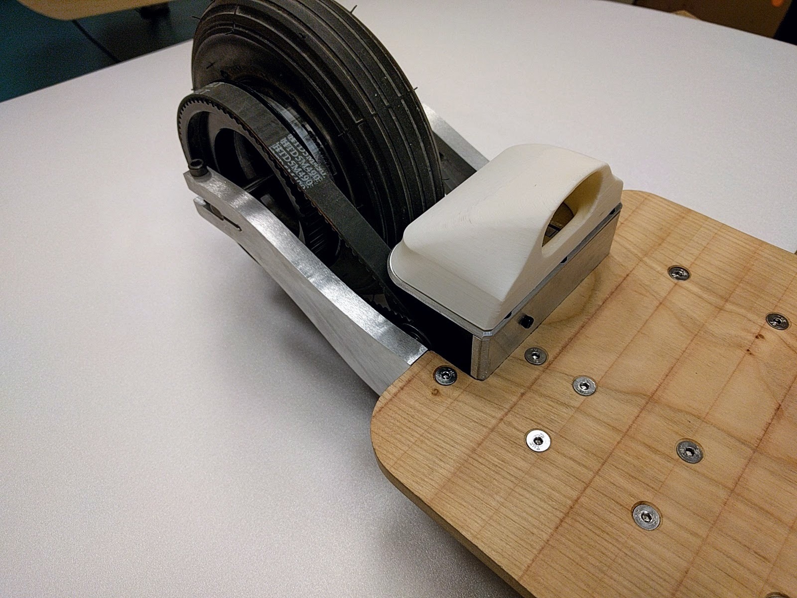
Decided battery compartment looked too much like a toaster so changed the design. ( I did make the mold and vacuum formed it, however. I learned I needed to make something with more draft angle so that I could remove it from the mold.) (Shout out to Spencer Bracamontes at GrabCad for the wheel assembly.)
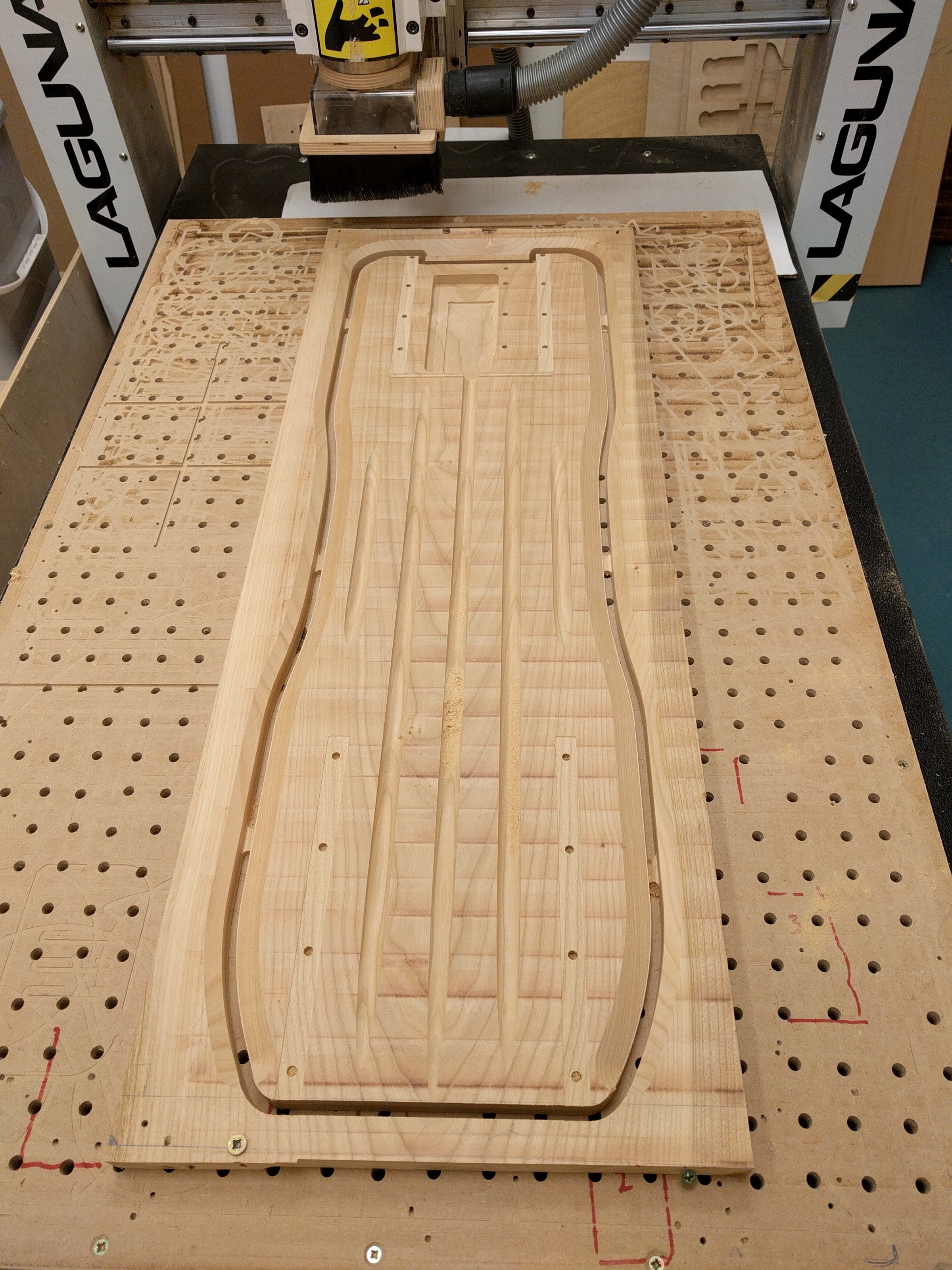
There is plenty of room for two 5.0 Ah lipos plus some wiring/connectors in the case above. I’ll be making the mold out of wood on the CNC then forming it with a vacuum forming machine using ABS plastic. I’ll be 3D printing a skirt that will fit under the case which will be connected to the deck. Not sure how to fasten case to it yet. Maybe some thumb screws. New to vacuum forming so we’ll see how that goes.
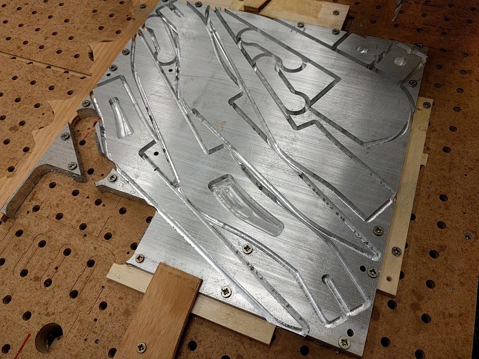
Have very little room to work on the 12" X 12" alu plate so fixturing is quite a puzzle. Still trying to deal with chip weld since I don’t have a mister/cooler.
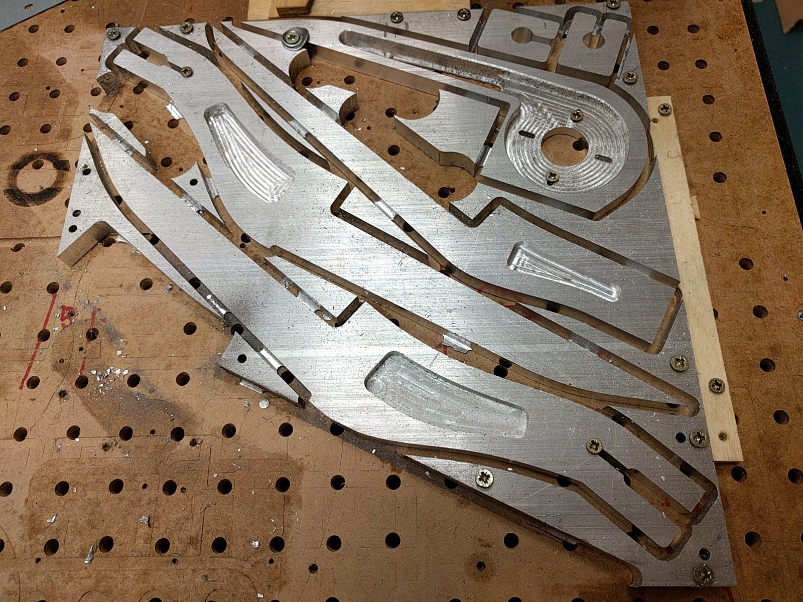
Spent a lot of time on the CNC yesterday. Got most of the parts cut out. Been using more oil to keep tool cooler and prevent chip welding. That seems to be working pretty well. Here are some pics:
Just realized a few minutes ago that I put the pocket for the motor mount on the wrong side. I’m all out of 1/2 inch aluminum stock. I think I have a solution using some 0.25" stock that I have. Back to CAD.
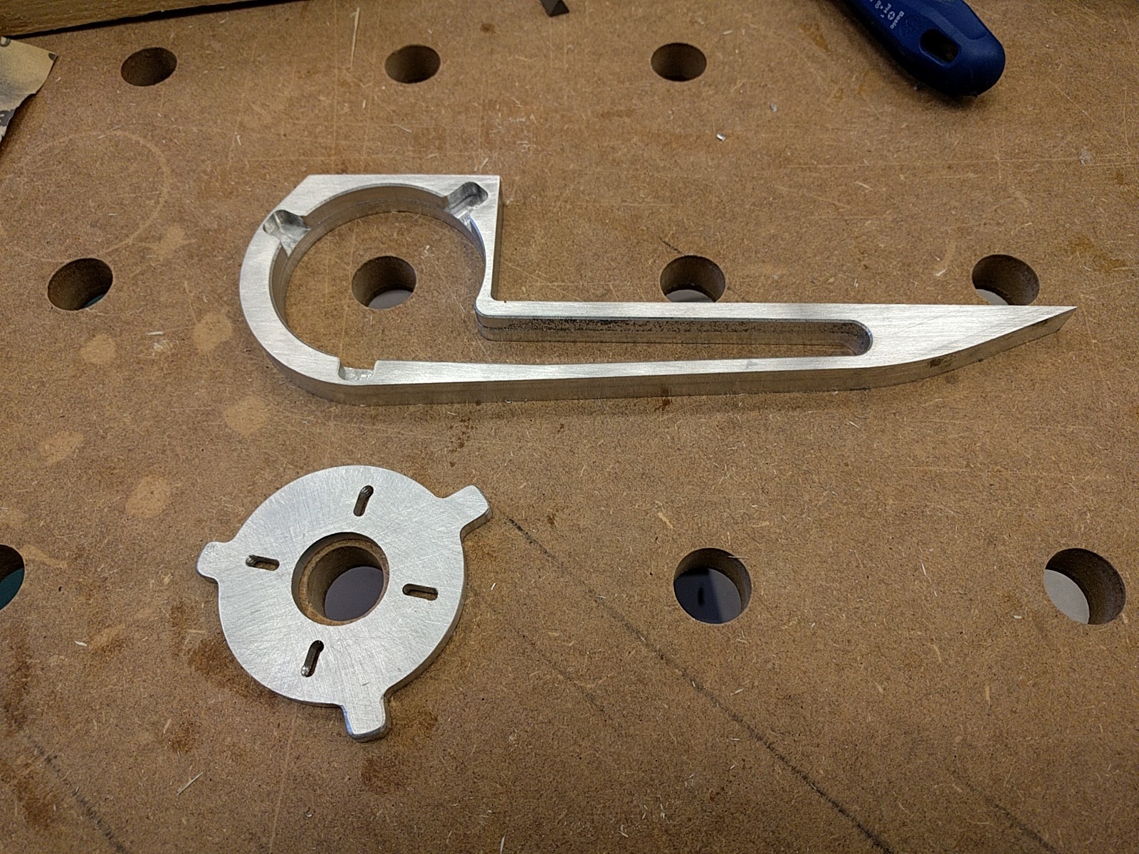
Okay. So I think the solution to putting the pocket on the wrong side of the motor mount came out okay. Would have preferred to have done it right, in the first place, but hey… Ended up taking all the material out of the motor void and then creating a part using .25 inch alu with tabs that sits into the void.
This is what it should have looked like from the the get-go. I guess on the upside, if I ever decide to use a motor with a different hole pattern, I can swap out the plate. This way, it’s kind of modular.
Your thread reminded me about this one from endless sphere, and I recently realised that I have 1 6374 spare motor, 1 spare ESC and enough cells to make 10S2P lipo pack, coincidence? I don’t think so
Wow… really nice work… keep it up and post the following result! I think in some way this is way better than 4 or 3 wheeled boards… Less weight, less Tire wear… better maneuvurability (possibly).
At least the ‘‘original’’ project author said it is quite good at low speed + stays stable at high speeds
There was this weird name called eboard which also used 2 wheels… Though the front was like ‘‘caster’’ wheel… will go to look it up now
I’m so hyped that actually right now am sketching my caster board project. I also found 60t 25H sprocket that would go nicely with trampa hypa hubs. It’s actually pretty simple desing to bring it to life, I was wondering last week or so what can I do with the spare parts, electric scooter or mono drive longboard were options, but THIS looks even simpler in my head.
I’m keeping my fingers crossed for OPs build and hopefully in some time I will show mine
Thanks for link to the two wheeler. Had not seen that one before.
Yeah, I think two wheels has some advantages over three or four like you mention above, but not sure how it actually performs. Wondering if it will have the same precise feeling of a trucked board. Would be nice it it doesn’t get wobbly at high speeds. We’ll see…
Hi. Thanks.
I’m using the Laguna IQ HHC. I agree; it’s the perfect size for this kind of thing. I think being smaller also helps make it a little stiffer, so better with aluminum. Not as good as a Tormach, I’m sure, for metals, but a good all-rounder for woods/plastics and metals.
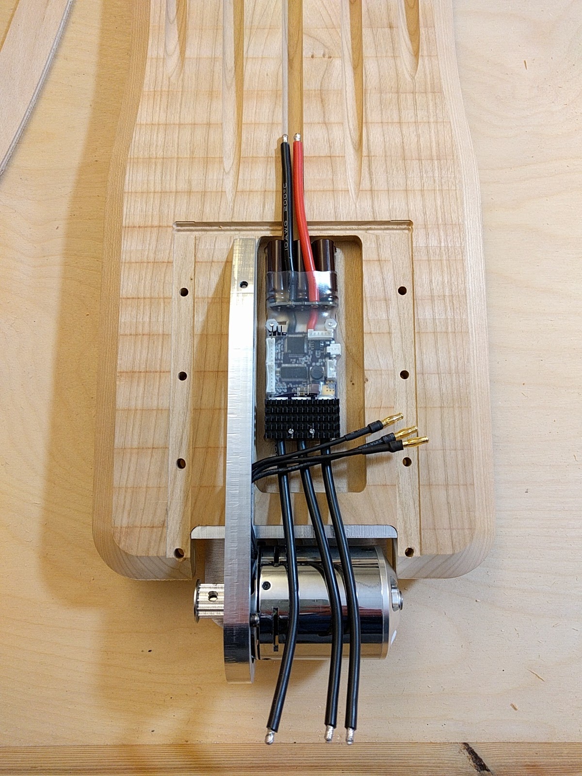
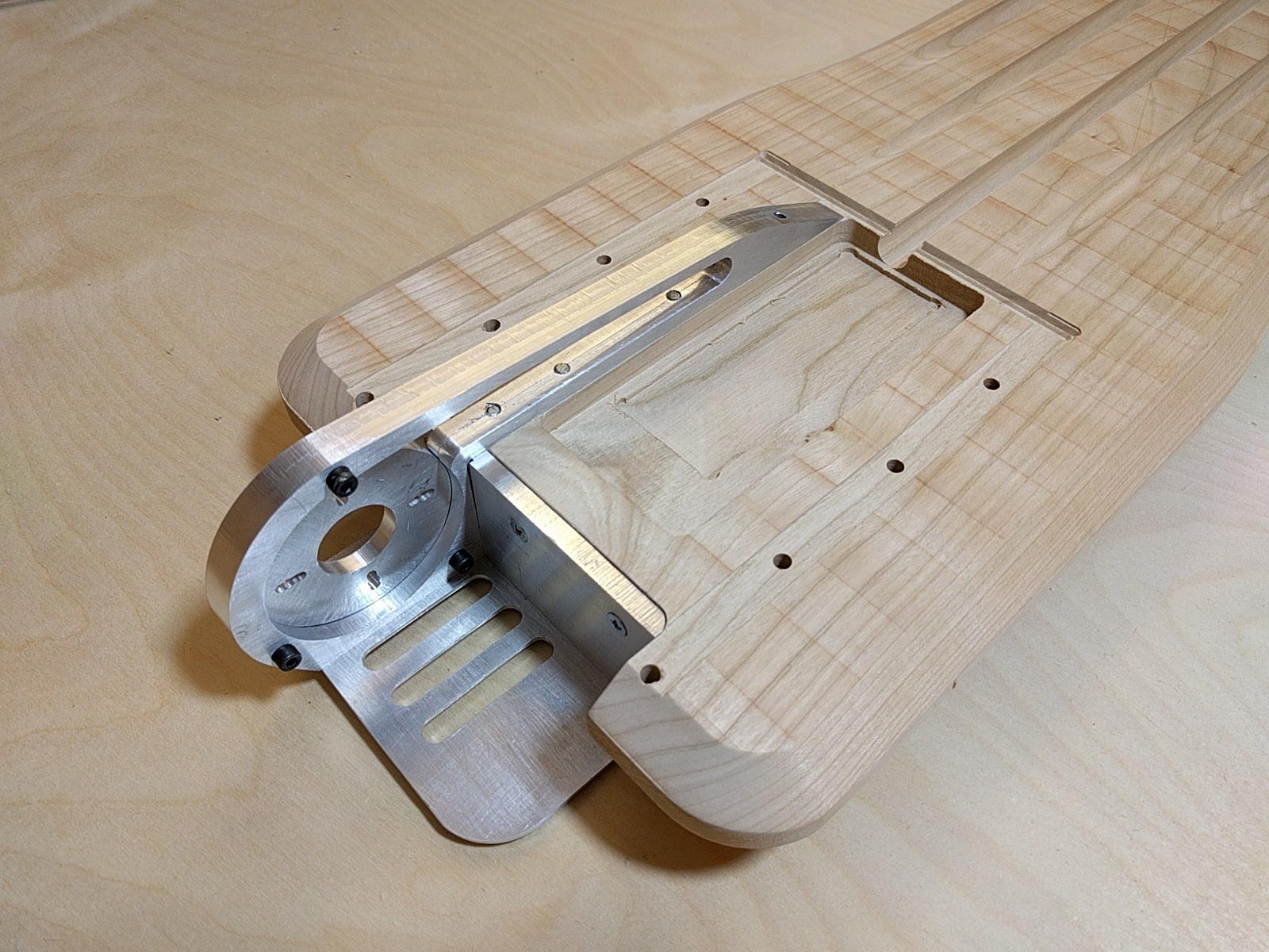
Got the motor mount assembly completed and all connected together. Feels like it’s going to be pretty sturdy. Lots of attachment points to deck. The pocket you see will hold the VESC and hopefully the receiver too. Planning on covering this whole area in 1/8" alu sheeting.
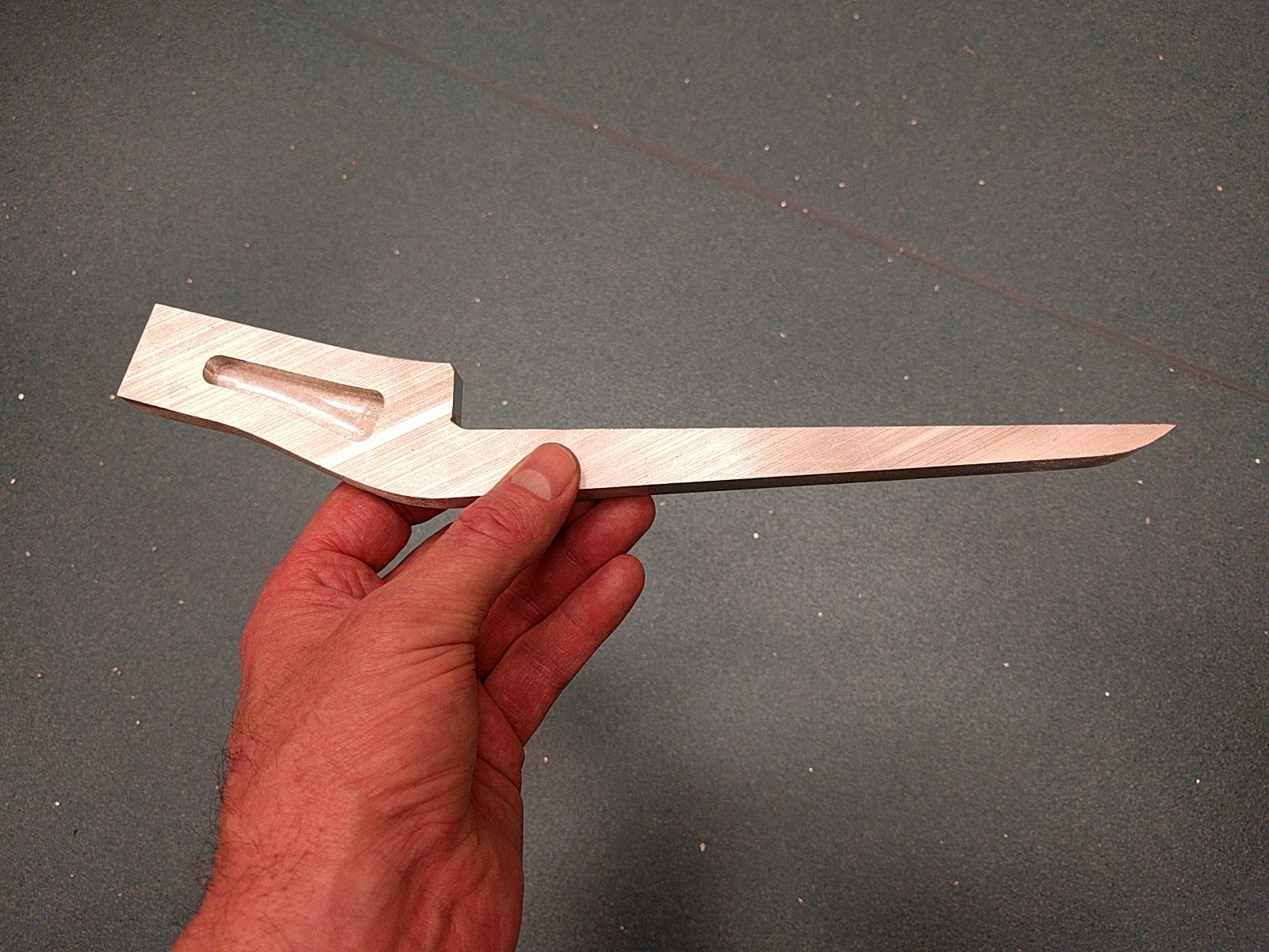
Been thinking of adding a foot grab in front in order to be able to lift front of board when needed (bumps, curbs, fashion poodles…) Any thoughts on this? Wondering if it’s just going to be painful if (when) I need to jump off the board fast. I’ve seen something similar on other boards. Also wanted to make it dual use as a handle. Seems like a pretty good place to pick up the board.
Also will be 3D printing an air scoop that should help ram air onto the motor. But really, doing it just because it looks cool. Thoughts on the foot lift appreciated.
That looks really cool. Can’t wait to see how this turns out. As far as the foot grab, how about just using a pair of the freebord bindings? The one you’re proposing looks really nice integrated into the board though. I think you would just need it to be sloped a bit like a shoe so it’s more ergonomic.
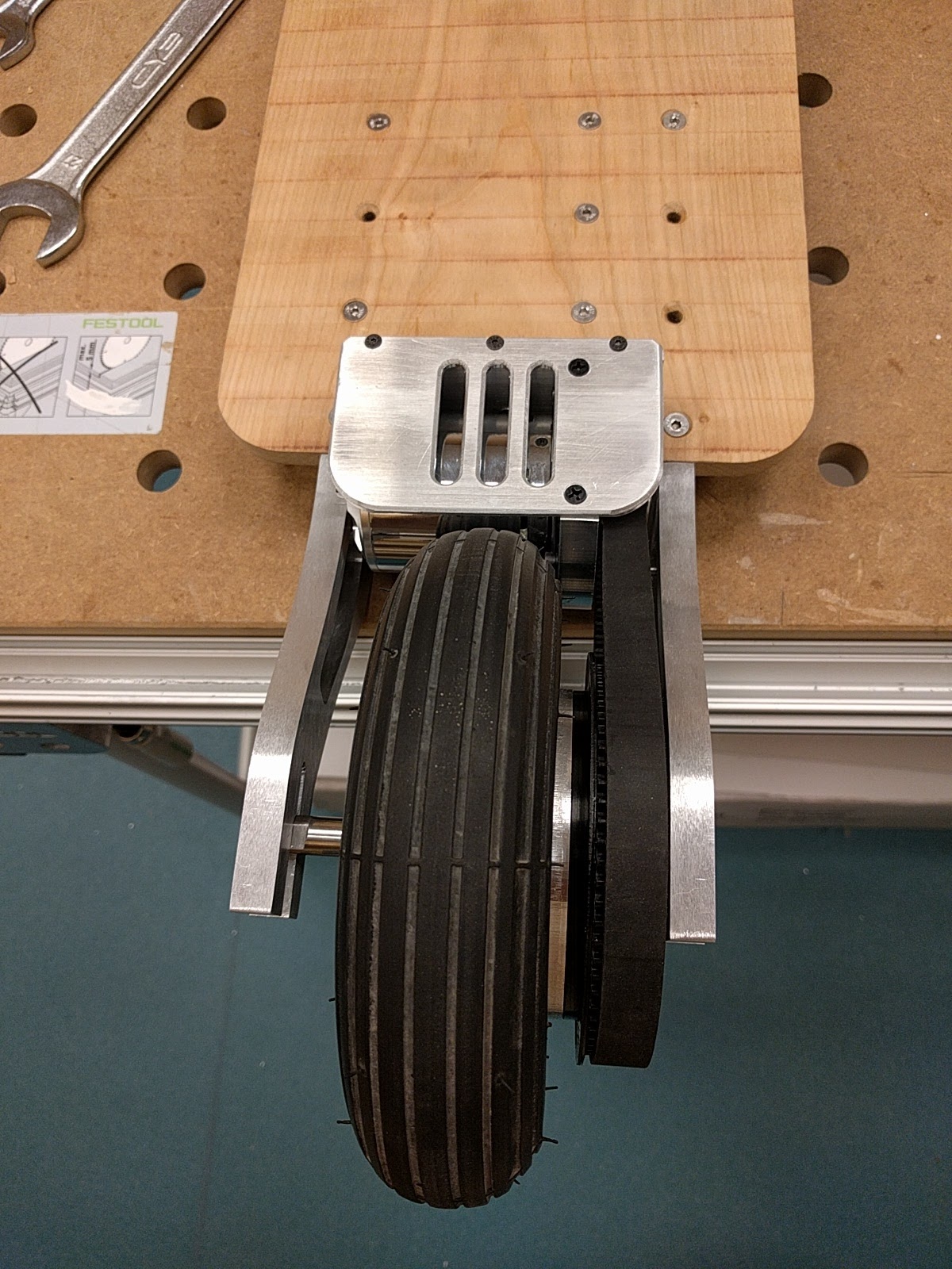
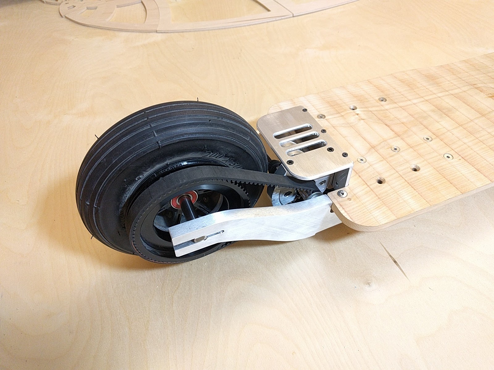
Got the struts connected to the deck. The struts will be sheeted over, covering this area. Not sure if I’m going to use ABS plastic or aluminum. The motor was longer than I had calculated in the CAD drawings so I had to remove a small pocket in the side of strut so that the end of the motor would not rub on the strut.
Wish I had a longer belt. Had to remove a little material from strut axle channel in order to move the wheel forward a couple mils so that the belt wouldn’t be too tight. Am using a 490mm belt. Could not find a 495 or 500 in the right width.
Had to make a spacer to move the wheel gear out to the side more, otherwise the wheel would not have been centered. 1/4 inch alu did the job.
Need to make some spacers to place on axle to keep wheel centered. Also still need to drill holes for the clamp-down bolts needed to hold the rear axle in place.
Been connecting many of the alu pieces together with hardware. Lots of measuring, drilling and tapping.
Here’s the front assembly. Still waiting for the correct size shoulder bolts. The ones I ordered before were a little short. Some of the bushings seem a little tight around the shoulder bolts I do have. Not sure of the best way to create a little more room in there. Tried drilling one out and adding some oil. Better but not great. Seems like this assembly needs to be very low friction but maybe not…


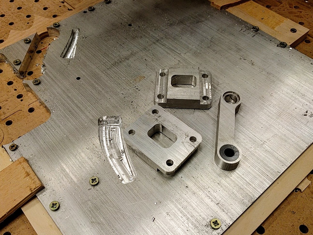

 I’m all out of 1/2 inch aluminum stock.
  I think I have a solution using some 0.25" stock that I have. Back to CAD.


 Thoughts on the foot lift appreciated.