Introducing the dual VESC made for simplicity.
This is a twin ESC designed and based off of the VESC 4.10.
Benefit:
compact design when compared to wiring 2 vesc to gether
Less soldering and wiring
Batteries input is shared between both ESC
Capacitors are pcb mountable at 45 or 90deg
Both ESC connected via can bus
1 USB input
Built in nrf24l01 footprint ready for nunchuk control
Reduced componants by
Both ESC share 3v and 5v power rail
Both share the 1 set of LEDs
And again 1 USB and reduces the need for installing jst plugs meaning a small componant reduction.
Foreseen problems:
3v and 5v Power rails not supplying enough amp
Batterie input traces not handling required current
Added cost of 6 layer pcb
(Please add more)
Ways we have tried to fix:
Made pcb 6 layer to allow 3layer thick power traces
Thread started for all positive and negative feed back please!
Nice !
This can’t be coincidence after @chaka mentioned a compact dual VESC in another thread
A dual VESC will need to be cheaper than two single ones for this to work.
Quality control and testing will also become more important because failure of one side will render the whole board practically useless.
I don’t know if this is feasible electronically but ideally you’d have one MCU controlling 2 independent sets of power MOSFETS. EDIT - strike that, it won’t work.
-5V rail, use both buck converters connected together with 2 diodes, small voltage drop but worth it if the the extra power is needed
-keep the led independent, very useful to know which DRV is sending the error code
-line up all of the fets bodies, to be able to stick a nice long heatsink on there, include heatink mounting holes?
-the power input tabs stick out like a sore thumb, directly put a XT60 connector footprint?
How will the USB detect both mcu, or is it just detecting one mcu and the second one is directly programmed by CAN? The issue I foresee is that we cannot control each motor independently… which is very handy in robotics, but maybe your not aiming for this market. Add some 0 ohm resistors on the CAN bus, because i am assuming they are connected together, add the second usb footprint as a place holder (vertical mount?)?
-inquire for 3-4oz copper on outter layers, can be less expensive than adding internal layers
-add some via stitching on the power track if you thing your tracks are to small, but i think your power tracks are superimposed, if it is the case, adding a stitch can be tricky/
-add solder mask on the no longer needed legacy power landings, unless you add some solder to those tracks
Ideally yes… but that’s not as easy as you would think, at least not yet, I think one of the biggest cost increases was the 6 layer PCB. This is somewhat countered by not having a separate PCB for the Caps.
So in the end there is really no reduction in cost. Which is fine by me.
The most exciting thing is its simplicity, Less soldering! As a builder of complete electric skateboards, I know that time is money, this could save 30-40mins per build which I will gladly pay a few dollars for that… For a one man band any time saving is extremely valuable.
They’re the old Flier style ones from Enertion’s late 2013 collection. I saved them so that one day i could maybe start replacing parts on them, but i haven’t yet. They’re monsters when they perform correctly.
But right now they’re dead and that’s leaving a nasty taste in my mouth where integrated dual ESCs are concerned.
Building on the original PCB design is still the most compact for a dual VESC. It needs to be fitted with vertical usb ports to make it work but only measures 80mm wide.
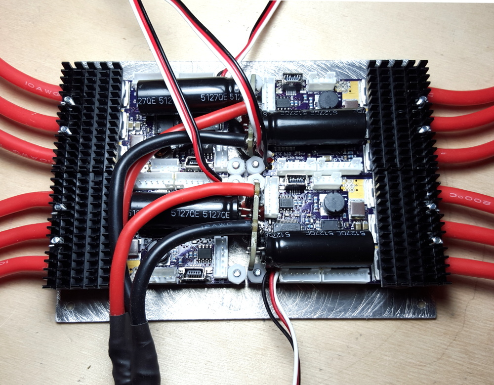
Here is a photo of a quad VESC with an extended base for mounting purposes. You would want the capacitor boards in their usual configuration on a dual VESC but it gives you a good idea of what you would see on a custom dual VESC.